Carillo (1942 and Asaoka (1978) developed Eq. 4.2 to express the average degree of consolidation for the case of combined horizontal and vertical consolidation. Note, however, that (1) the small distance between the drains (the drain spacing), (2) that the horizontal coefficient of consolidation, ch, is larger than the vertical coefficient, cv, and (4) the fact that the thickness of the clay layer is normally much larger than the drain spacing. The combined effect of this is that the effect of vertical drainage is normally insignificant.
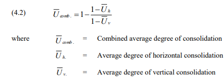
For example, if the horizontal degree of consolidation in the absence of vertical flow is 80 % and the vertical degree is 20 % in the absence of horizontal flow, the combined degree is 75 %, which is not that much smaller than the horizontal degree alone.
Practical Aspects Influencing the Design of a Vertical Drain Project
In addition to the theoretical aspects, a design of a vertical drain project is affected by several practical matters, as outlined in this section.
Drainage Blanket on the Ground Surface and Back Pressure
Unless the drains are taken into a free-draining soil layer below the fine-grained layer to be drained, the ground surface must be equipped with a drainage blanket and/or trenches to receive and lead away the water discharged from the drains. Drainage of the “below” layer is rarely assured and, therefore, most projects will include a drainage blanket on the ground surface. Sometimes, the natural ground may provide sufficient drainage to serve as the drainage blanket. Absence of a suitable drainage blanket may result in water ponding in the bowl-shaped depression that develops as the soil settles, creating a back pressure in the drains that impairs the consolidation process. This is illustrated in Fig. 4.4. Ponding due to insufficient horizontal drainage on the ground surface is not acceptable, of course. In a design of a vertical drain project, the expected amount of settlement must be calculated and a surface drainage scheme designed that ensures a horizontal gradient away from the treated area at all times.

The build-up of back pressure will halt or slow down the time development of the consolidation settlement, which, if the process is monitored, is discernible as a flattening out of the time-settlement curve or a curve with a humpback appearance. This may lead to the false conclusion that all of the primary settlement has been obtained. However, eventually, the back pressure will disappear, and the settlement, delayed due to the back pressure, will recur. If the back-pressure is temporary, the settlement versus time curve will show a hump back, a slow-down followed by an increase of the settlement rate.
It is also important to realize that as the embankment settles, the total vertical stress imposed to the original ground surface over and above the existing vertical stress reduces accordingly, which the modeling needs to take into consideration (because the height of the original ground surface above the groundwater table reduces). This is particularly important where the groundwater level lies close to the original ground surface.
Effect of Winter Conditions
In areas where Winter conditions prevail, consideration must be given to the risk of the ground frost reducing or preventing the drain discharge at the groundwater table or into the drainage blanket at the ground surface building up a back pressure. The result is similar to that of ponding: a slow-down of the settlement, which can be mistaken for the project having reached the end of the primary consolidation. After the Spring thaw, the settlement will recur.
Depth of Installation
The installation depth is governed by several considerations. One is that drains will not accelerate consolidation unless the imposed stress triggering the consolidation brings the effective stress in the soil to a value that is larger than the preconsolidation stress. i.e., the imposed stress is larger than the preconsolidation margin. The imposed stress decreases with depth (as, for example, determined by Boussinesq formulae; Chapter 3). From this consideration, the optimum depth of the drains is where the imposed stress is equal to the preconsolidation margin. However, other considerations may show that a deeper installation is desirable, e.g., to assure water discharge into a deeper located pervious soil layer.
Width of Installation
Drains installed underneath an embankment to accelerate consolidation must be distributed across the entire footprint of the embankment and a small horizontal distance beyond. A rule-of-thumb is to place the outermost row of the drains at a distance out from the foot of the embankment of about a third to half the height of the embankment. If the drains are installed over a smaller width, not only will differential settlement (bowing or dishing) increase during the consolidation period, the consolidation time will become longer.
Effect of Pervious Horizontal Zones, Lenses, Bands, and Layers
The assumption of only homogeneous soil, whether with only radial flow or radial flow combined with vertical flow, used in the derivation of the formulae is not realistic. In fact, most fine-grained clay soils contain horizontal zones of pervious soil consisting of thin lenses, bands, or even layers of coarse-grained soil, such as silty sand or sand. These layers have no influence on the consolidation process where and when no drains are used. However, where vertical drains have been installed, the drainage is to a large extent controlled by the vertical communication between these zones as facilitated by the drains. As illustrated in Fig. 4.5, the consolidation is then by way of slow vertical flow in the fine-grained soil to the lenses, followed by rapid horizontal flow in the lens to the vertical drain, and, then, in the drain to the surface blanket. In effect, the lenses take on the important function of drainage boundaries of the less pervious layers of the soil body sandwiched between the lenses. That is, the mechanism is still very much that of a vertical flow.

It is vital for a design of vertical drain project to establish the presence of such lenses, bands, or layers of coarse-grained soil and their vertical spacing. Conventional boreholes and laboratory analysis of recovered samples are rarely fully suitable for this purpose and, usually, once it becomes clear that vertical drains are considered for a project, additional field investigation involving both undisturbed sampling, CPTU tests, and special laboratory testing may become necessary.
Comments are closed