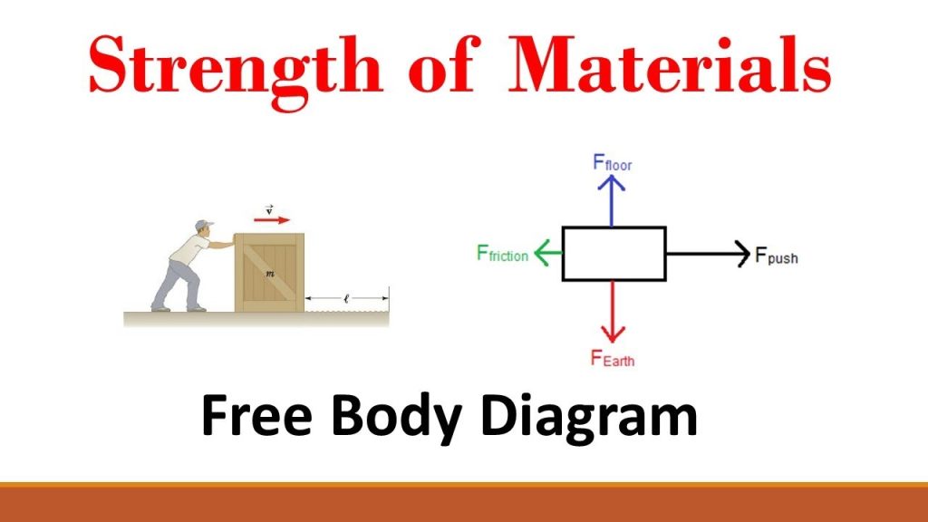
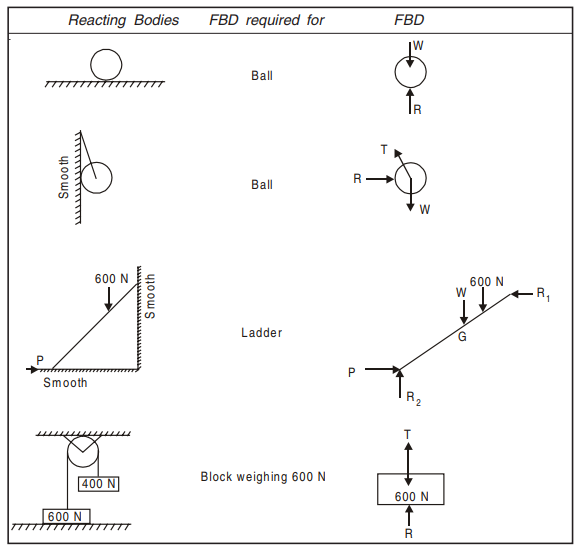
In many problems, it is essential to isolate the body under consideration from the other bodies in contact and draw all the forces acting on the body. For this, first the body is drawn and then applied forces, selfweight and the reactions at the points of contact with other bodies are drawn. Such a diagram of the body in which the body under consideration is freed from all the contact surfaces and shows all the forces acting on it (including reactions at contact surfaces), is called a Free Body Diagram (FBD). Free Body Diagrams (FBD) are shown for few typical cases in Table 2.2.
Table 2.2 Free Body Diagrams (FBD) for a Few Typical Case
Equilibrium Of Bodies
A body is said to be in equilibrium when it is at rest or has uniform motion. According to Newton’s law of motion, it means the resultant of all the forces acting on a body in equilibrium is zero. The resultant of coplanar system of forces acting on a body is zero when
(a) The algebraic sum of the component of forces along each of the two mutually perpendicular directions is zero (translatory motion is zero).
(b) The algebraic sum of moment of all the forces about any point in the plane is zero (rotational moment is zero).
The above conditions for coplanar concurrent and non-concurrent forces is discussed and illustrated in this article.
Equilibrium Of Concurrent Force Systems
If the moment equilibrium condition is considered about the concurrent point of application of the forces, the equation results into zero equal to zero. Hence this is not at all a useful equation. Thus only the conditions to ensure translatory motion is zero gives useful equations. In planar problems the resultant R of a system of forces is zero only when the following conditions are satisfied.
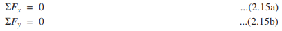
It may be observed that only one of the above two conditions is not sufficient. For example, ΣFx = 0 means that R cos α = 0. This will ensure that the resultant R cannot exist in any direction except in y-direction (α = 90°). Hence the condition ΣFy = 0 also should be satisfied to ensure the resultant R does not exist, that is, the equilibrium condition exists. After drawing free body diagrams for each of the body under the action of concurrent force system equations 2.15a and 2.15b may be written and the problems may be solved.
If a body is in equilibrium under the action of only three concurrent forces, Lami’s theorem also may be used.
Lami’s theorem states : If a body is in equilibrium under the action of three forces, each force is proportional to the sine of the angle between the other two forces.
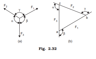
Thus, for the system of forces shown in Fig. 2.32(a)

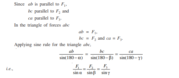
Proof: Draw the three forces F1, F2 and F3 one after the other in direction and magnitude starting from point a. Since the body is in equilibrium (resultant is zero), the last point must coincide with a. Thus, it results in triangle of forces abc as shown in Fig. 2.32(b). Now, the external angles at a, b and c are equal to β, γ and α
Note: While determining the direction of the reaction on a body note that if the body is in equilibrium under the action of only three coplanar forces, those three forces must be concurrent.


Comments are closed