Considerable length of rural roads has been constructed under a host of rural development programmes, especially Community Development Programmes for Rural Roads, Food for Work Programme, Minimum Needs Programme (MNP), etc. An impetus was further given by allocating more funds under schemes, such as, National Rural Employment Programme (NREP), Rural Landless Employment Generation Programme (RLEGP) and Jawahar Rozgar Yojana (JRY). Inspite of all these efforts, rural connectivity still remains quite poor, with several States having below 50 per cent rural connectivity. The network developed by the criteria of qualifying populations does not take necessarily into account the travel requirements of unconnected habitations, which results in sub-optimal road network. Thus, the roads in an area should be considered together with the accessibility requirements ofthe habitations, and every unconnected habitation should be provided with connectivity through at least one road link, which meets its socio-economic requirements. A habitation can be defined as a cluster of population, living in an area, the location of which does not change over time.
A habitation is considered connected only if it has an access through all-weather road. Allweather road is an engineering structure built using proper specification and design and with various cross drainage works as per the requirements except major river crossings. Interruptions to the traffic as per permitted frequency and duration are, however, allowed. The interruption is allowed six times a year with maximum one day at a time; or maximum of 72 hours in case another alternative access is available. A road, though usable for most of the time, but traffic gets disrupted during rainy season due to lack of all cross drainage works, is called a fair-weather road.
Various departments, under different programmes without a common network development objective take up the construction of rural roads, and therefore, it results into a sub-optimal network. Consolidated programme of developing an optimal network of roads based on a master plan will provide rationality of choice and can save any wastage of resources. The network plan or master plan needs to be prepared at a level which is convenient from the point of map preparation and data collection. Thus, the Master Plan data for rural road network should be collected/prepared at Block level and then integrated for a District level Master Plan.
Planning Database
Database development:
In order to prepare a scientific Master Plan for rural roads, it is necessary to build a comprehensive database for all habitations and the existing network of all types of roads and tracks, preferably in the computer environment. The first step in preparation of Master Plan would be to collect all the information available at district, block and habitation level from secondary sources. The next step is to collect the detailed information on each habitation and road link through field surveys. Various data items required for developing the rural road plan can be broadly identified under three categories:
1. Habitation level data,
2. Road inventory data, and
3. Map data
Habitation level data : A village/settlement/habitation located within a distance of 500 metres from an all-weather road or a connected settlement/habitation may be considered to be already connected. All habitations/settlements having population more than 100 and which are located more than 500 metres (half-akilometre) away from each other or from an all-weather road should be separately identified. The habitation level data will include details on demographic (population) and infrastructure facility data (socio-economic functions or facilities available in habitation/settlement), which should be collected for each habitation. This may be obtained from the secondary sources, such as, census records, revenue records, etc. and collected at Block level.
Road inventory data : A comprehensive inventory of all rural roads including Other District Roads s (ODR) and Village Roads (VR), and any other road constructed/improved under various rural development programmes, such as, RLEGP, NREP, MNP, JRY, sugarcane roads, mandi road, etc. have to be prepared at Block level. For each road, the information on road geometric, road pavement condition, terrain, soil type and habitations connected by the road are to be collected. All the available alignments of cart tracks, footpaths, kutcha road, jeepable roads, etc., which have 5 metres or more land width, should be included for preparing road inventory. In addition to this, the National Highway (NH), State Highway (SH) and Major District Road (MDR), which form the primary and secondary road network in a region (say Block), will also be required to be inventoried for proposing connectivity of habitations.
Map data : The base map at Block level should be prepared at 1:50,000 scale by taking Survey of India topo-sheets as the base. Generally, maps used for planning are in much more detailed scale, however, due to non-availability of such maps, 1:50,000 scale will suffice. If available, the aerial photos and satellite imageries, etc. can also be used to further improve the accuracy of the map. The data that are collected as per the three formats at Block level are to be transformed into maps by drawing Block maps and incorporating all the information, such as, habitations and road locations. The map should show the Village, Block, District and any other higher order boundaries, it should show all types of roads (National Highways, State Highways, Major District Roads, Other District Roads, Village Roads and all other roads and cart tracks built under various programmes of the State and Centre) as per the inventories.
Digital maps : Digital maps with proper registration, etc. should be prepared when the master planning is to be done in a computerised environment. For computerisation of the data (map, road inventory and habitation data), a Geographic Information System (GIS) platform may be used. However, the data and analysis at Block level can be very easily managed manually also
Concept of Network Planning
Network philosophy :
Rural roads are part of the total road network system. A road network basically consists of links (roads of various categories, such as, National Highways, State Highways, Major District Roads, and Rural Roads). Roads, therefore, become links of a network, which facilitate the essential movements of persons and goods in an area (say Block or District), and no individual road link can serve the same purpose when developed in isolation. A road network, therefore, needs to be developed in such a way that the travel needs of the people or u.j community in an area are met to the maximum in a collective way at the lowest cost of development. In the rural areas, major part of their travel needs is comprised of travel to market place, education centre and health centre (almost 95 per cent of total travel needs). Thus, creation of an optimal road network is to be aimed to serve the habitations for access to such needs through a Master Plan. X IRC:SP:20-2002 While attempting to optimise the road network, each unconnected habitation has to be connected to the existing all-weather road network or already connected habitations in an efficient way (in terms of cost and its utility). There are a large number of methods to develop optimal network for rural roads. However, in practice, very little or no use of those have been possible so far, primarily due to non-availability ofrequired data and the Master Plan. The concept and methodology described in this section is based on the objective of integrated development and accessibility for rural habitations. While the method is simple, it can be operationalised with minimum data.
Utility value : Traditionally habitations have been provided priority for an all-weather road connection solely based on its population size. The Second and Third 20-Year Road Development Plans of Indian Roads Congress also recommended distinct population criteria for village connectivity. However, the integrated development approach aims to provide the habitations with access to various service facilities, and it requires a different criterion based on a composite measure or index or utility value. The utility value for the habitation should consider a set of demographic, socio-economic, infrastructure, and level of development data. This composite measure of development may be called as Utility Value (UV) of the habitation. Selection of the variables for computing the utility value may be made from the habitation level data. The chosen set of variables may be different in different parts of the country based on local development aspirations. Each variable can be given a weightage based on its present level and importance in the integrated development philosophy. An example of the choices for weights is presented in Table 1.1. Table 1.1.
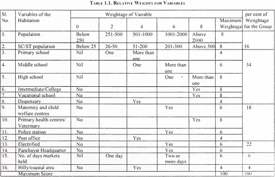
Utility value is required to be calculated for all habitations, large and small, with population size 100 and above using the data collected in FORMAT-I. The computed utility value may be used for the prioritisation of habitations. For ease of computation, the facilities (functions) given in Table 1.1 may be grouped appropriately; and one such possibility is shown here:
(i) Primary and middle school
(ii) High school, intermediate and vocational school
(iii) Medical and veterinary facilities
(iv) General infrastructure, such as, post and telecommunication, police station, bus service, electrification, local administration, etc.
(v) Commercial establishments including industrial units (e.g., handlooms, handicrafts, sugar mills, etc.) The grouped facilities will have to be assigned weights for different levels of development.
Development of links :
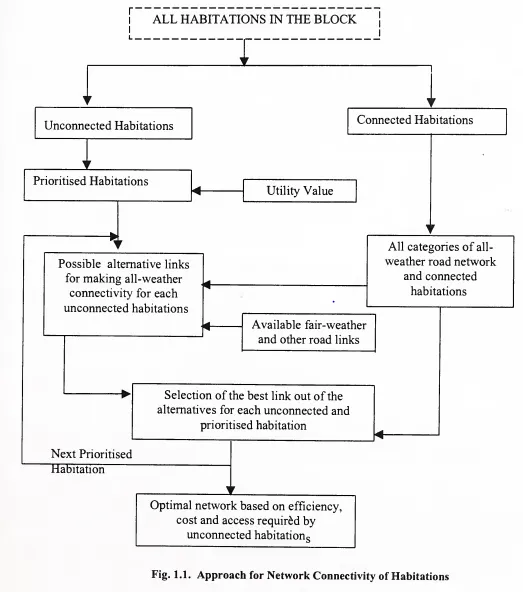
The available options of connectivity for habitations shall be guided by certain assumptions as given below in order to develop a road network, which adequately meets the accessibility requirements of the unconnected habitations:
(i) The population of unconnected habitations shall have to travel to nearby habitations to fulfil their locally unsatisfied needs (utility services).
(ii) The unconnected habitations may be presently connected through fair-weather road links which may have to be upgraded for all-weather connectivity, or by a new link from the unconnected habitation to an all-weather link or a connected habitation.
(iii) The choice of linkage shall be based on network philosophy and at a minimum cost. The above assumptions are the basis for the development of rural road network in a Block or a District in a structured manner as described in Fig. 1.1. Guidelines given in IRC:SP:48 ‘Hill Road Manual’ can also be referred for hill areas. By arranging all the unconnected habitations in descending order of the Utility Value, and fixing a cut- off value, prioritised order of habitations may be identified. The population of unconnected habitation will generally go to a habitation having the required utility services (facilities) within a reasonable influence area through a shortest route. From the several possibilities based on available fair-weather roads/tracks, etc. or new alignments of shortest length to nearest all-weather road or an already connected habitation, suitable options are to be identified for selection of the best link option. The best link option shall be the one with highest benefit that it offers in terms of potential utility of that connectivity. The benefit offered by a link is going to be directly proportional to the population sizes of all the habitations it serves or indirectly in proportion to the Utility Values (UV) of the habitations. If a road link serves more than one unconnected habitation, a weighted average of Utility Values may be adopted based on the portion of length of the proposed link that will be used by each of these habitations. The cost of a link will depend on the link length and the type of improvement (when it is an existing fair-weather road or a track) needed to make it an all-weather link or the cost of the new link. The choice of the link shall be based on the corresponding access benefit-cost ratios for the options evaluated.
Rural Roads Plan
The district rural roads plan is a combined Master Plan of all the Blocks for which the optimal network links for the unconnected habitations are shown in the descending order of priorities. Block-wise prioritised list ofroads for next 5 to 10 years shall be prepared, and all the Blocks in a District are to be considered together for District level Master Plan to be prepared (considering appropriately the development priorities for the roads 10 IRC:SP:20-2002 running across the Blocks). However, in the District Master Plan all the Blocks will be available separately also with all information at Block level, so that the implementation of road programme is possible at Block level. Thus, based on the budget available the number of links can be selected from the list of prioritised links for taking up in a given year or any suitable plan period. The chosen links for development in a given year shall be further studied for detailed project planning and preparation of estimate.
Road Alignment and Surveys
The alignment of rural road should be decided only after conducting proper surveys and investigations. In general, most new roads will also have to follow the existing cart tracks and other such existing alignments. However, during route location the following points should be considered:
(i) Adoption of appropriate geometric design standards and safety requirements
(ii) Keeping to the high ground so as to avoid low lying areas and minimising the drainage requirements
(iii) Following the land contours as far as practicable to reduce the extent of cut and fill
(iv) Conforming to any property boundaries to the extent possible
(v) Avoiding or minimising the effect on vegetation
(vi) As far as possible, alignment should not interfere at any stage with services, like, power transmission lines, water supply mains, etc.
Following special considerations are to be given due importance for the alignment in mountainous terrain:
(i) When crossing mountain ranges, the road should preferably cross the ridges at their lowest elevation. In certain cases, it may be more expedient to negotiate high mountain ranges through tunnels. This decision should be taken after considering the relative economics or the strategic requirements.
(ii) While fixing the alignment the introduction of hair-pin bends should be avoided as far as possible. In unavoidable cases, the bends should be located on staLie and flat hill slopes in due consideration of geometric design. Also, a series of hair- pin bends on the same face of the hill should be avoided.
(iii) As far as possible, attempt should be made to avoid unstable hill features, areas having perennial/potential landslide or settlement problems, areas subject to seepage/flow from springs, hydel channels, etc. For details. Hill Road Manual (IRC:SP:48) should be referred.
While deciding the alignment of a road, rural road development in reference to the objectives of Road Development Plan ‘Vision 202 1 ‘ of MoRT&H need to be borne in mmd before undertaking further investigation and subsequent fmalisation of the alignment. The location or the layout of the centre line of the road on the ground is called the alignment. The horizontal alignment includes the straight path, the horizontal deviations and curves. Changes in gradient and vertical curves are covered under vertical alignment of road. A new road should be aligned very carefully, as improper alignment would mean either capital loss initially in construction as well as recurring loss in cost of maintenance and vehicle operation. Once the road is aligned and constructed, it is not easy to change the alignment due to increase in cost of adjoining land and construction of costly structures by the roadside. The ideal alignment between two points should satisfy requirements as given under :
(i) Short: It is desirable to have a short (or shortest) alignment between two terminal stations. A straight alignment would be the shortest, though there ma be several practical considerations, which would require deviations from the shortest path.
(ii) Easy: The alignment should be such that it is easy to construct and maintain the road with minimum subsequent problems. Also, the alignment should be easy for the operation of vehicles with easy gradients and curves.
(iii) Safe: The alignment should be safe enough for construction and maintenance from the viewpoint of stability of natural hill slopes, embankment and cut slopes and foundation of embankment. Also, it should be safe for the traffic operation in terms of safe geometric features.
(iv) Economical: The road alignment would be considered economical only if the total cost including initial cost, maintenance cost and operational cost, is the lowest.
(v) Sound: The alignment should be on the firm ground and should not be susceptible to large settlement, deformation, landslide, etc.
(vi) Aesthetics: While selecting the alignment, the aesthetics of the area should be borne in mind.
(vii) Environment: The alignment should be decided giving due weightage to environment protection, particularly in hilly areas. Tree cutting should be avoided as far as possible by suitably locating the road alignment.
Governing Factors for Route Selection
General considerations:
Ø The alignment should be as direct as possible so that there is maximum economy in cost of construction, maintenance and transportation.
Ø The grades, curvatures and profiles should be so designed as to be economical, consistent with the service requirements.
Ø While improving the existing alignment, the endeavour should be to utilise the existing facility as much as possible in order to minimise the cost and effort of land acquisition and construction.
Ø The alignment should not interfere at any stage with services, like, power transmission lines, water supply mains, etc.
Ø Embankment and pavement account for major proportion of the road cost; therefore, availability of material for embankment and pavement construction should be kept in view while finalising the alignment. Similarly, good subgrade conditions would mean lower pavement cost and thus the subgrade conditions also affect the choice of alignment. To the extent possible, areas susceptible to subsidence (due to mining, etc.), marshy and low lying areas prone to flooding, inundation and erosion should also be avoided.
Ø While connecting population centres, the alignment should preferably skirt round the population pockets rather than pass through congested areas.
Factors Controlling Alignment :
The various factors, which control the road alignment, may be listed as:
a) Obligatory points
b) Traffic
c) Geometric design
d) Economics
e) Drainage
f) Other considerations
Obligatory points :
There are control points governing the alignment of the roads. These control points may be divided broadly into two categories :
A. Points through which the alignment is to pass
B. Points which the alignment should avoid.
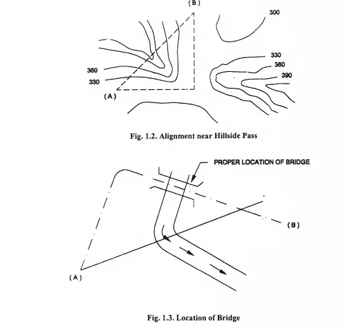
Obligatory points through which the road alignment has to pass may cause the alignment to often deviate from the shortest path. The various examples of this category may be a bridge site, intermediate town, a mountainous pass or a quarry. When it is necessary to cross hill mountains or high ridges, the various alternatives are to cut a tunnel or to go round the hills or to deviate until a suitable hill pass is available. The suitability of these alternatives depends on many other factors, like, the topography and site conditions. Fig. 1 .2 shows how the straight alignment AB is deviated along the hillside passes thus avoiding a tunnel or heavy cutting. The road bridge across a river should be located only at a place where the river is straight and has firm banks and where the bridge abutment and pier can be properly founded. The road approaches to this bridge should not be on curve near the bridge and as far as possible skew crossing should be avoided as shown in Fig. 1 .3. Thus, in order to locate a bridge across a river the road alignment may have to be changed. Similar is the case with the railway crossing. As far as possible, at unmanned level crossing the alignment shall be straight. Besides, it shall be ensured that there are no features on the ground, which would obstruct the visibility. The site for the level crossing may invariably be decided in consultation with the railway authorities.
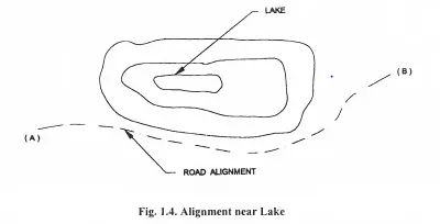
Obligatory points through which the road should not pass also make it necessary to deviate from the proposed shortest alignment. The obligatory points, which should be avoided while aligning a road, include religious places, very costly structures, unsuitable land, etc. Religious places include temples, mosques, churches, graves, tombs and archaeological places, reserve forests, etc. Acquiring costly structures would mean heavy compensation resulting in increased cost. Marshy, peat and waterlogged areas are generally unsuitable for road construction and should be avoided as far as possible. However, if there is no alternative and the alignment has to be taken across such an area, the construction and maintenance costs are likely to be very high due to special construction techniques to be adopted. A lake, a pond or a valley, which falls on the path of a straight alignment, will also necessitate the alignment to deviate from the straight path and go round along the lake as shown in the Fig. 1 .4.
Traffic : In most of the cases, the people use certain routes traditionally. These may either be due to convenience, social connection with other areas, etc. The proposed alignment should keep in view this traffic flow pattern. At the same time one should also have a fair judgement of future trends in mind.
Geometric designs : Geometric design factors, such as, gradient, radius of curve and sight distance would also govern the final alignment of the road. As far as possible, steep gradient should be avoided and limited to the ruling or design gradient. Thus, it may be necessary to change the alignment in view of the design, speed and maximum allowable super-elevation. It may be necessary to make adjustments m the horizontal alignment of roads keeping in view the minimum radius of curve. The absolute minimum sight distance, which should invariably be available in every section of the road, is the safe stopping distance for the fast moving vehicles. Also, there should be enough distance visible ahead for safe overtaking operations of vehicles. Hence, the alignment should be finalised in such a way that the obstructions to visibility do not cause restrictions to the sight distance requirements.
Economy : The alignment finalised based on the above factors should also be economical. Avoiding high banking, deep cutting, major crossing and balancing of the cuts and fills can decrease initial cost of construction. At the same time, care should be taken to see that it is not likely to involve costly maintenance and operational expenses.
Other considerations : Various other factors that may govern the alignment are drainage considerations, hydrological factors, social obligations, etc. The vertical alignment (particularly the gradient and change of grade) is often guided by drainage considerations. The sub-surface water level, seepage flow and high flood level are also the factors to be kept in view.
Special Consideration for Hill Roads In hill roads, additional care has to be taken for ecological considerations, such as:
(i) Stability against geological disturbances
(ii) Land degradation and soil erosion
(iii) Destruction and denudation of forest
(iv) Interruption and disturbance to drainage system
(v) Aesthetic considerations
(vi) Siltation of water reservoirs
Special care should be taken to align the road along the side of the hill, which is stable. A common problem in hill roads is that of landslides. The cutting and filling of earth to construct roads on hillside causes steeping up of existing slopes which affects its stability. Hillside drains should be provided for adequate drainage of water across the road. But since the cross drainage structures are costly, attempt should be made to align the road in such a way that the number of cross drainage structures are minimal. Different geometric standards are followed in hill roads with reference to gradient, curves and speed, and they consequently influence the site distance, radius of curve and other related features. The selected route should be feasible from the point of attaining the ruling gradient. The alignment should involve least number of hair-pin bends and wherever unavoidable, these should be located on stable and less steep slopes. In hilly areas locations which get sunlight should be preferred over locations in the shade. The areas liable to snow should be avoided. For selection of road alignment in hilly area, reference may be made to Hill Roads Manual (IRC:SP:48).
Special Consideration in Sand Dune Areas
The road should be so located that it causes minimum interference to the flow of sand-laden winds. Therefore, the roadway should merge with the line of the land as much as possible. In areas having longitudinal sand dunes, a location along the ridge or in the inter-dual space should be preferred. Location along the face of the dunes should be avoided. Locations where sand is loose and unstable should be avoided.
Surveys
Final location of the alignment is based on ground verification, and therefore, the engineering surveys are to be carried out. The surveys may be completed in four stages as below:
(i) Reconnaissance
(ii) Preliminary Survey
(iii) Determination of Final Centre Line
(iv) Final Location and Detailed Survey To facilitate the survey team in the tentative selection of alternative alignments for subsequent detailed ground reconnaissance, it will be advisable, to make use of modern techniques, like, aerial survey, photogrammetry and remote sensing.
Reconnaissance :
Keeping in view the obligatory points the next step will be to undertake reconnaissance survey in the following sequence:
a) Study of topographical survey sheets, revenue maps, geological and meteorological maps, and aerial photographs where available
b) Preliminary aerial survey reconnaissance (as against Aerial Photographs), where practicable
c) Ground reconnaissance
d) Final reconnaissance of inaccessible and difficult stretches
Study of survey sheets and maps : The study of topographical maps available in the scale of 1 :50000, i.e., 2 cm to 1 km showing towns, villages, rivers and terrain features with altitudes and contour lines at interval of 20 m and revenue maps may be useful to locate the obligatory and control points and to mark the probable alternative feasible routes on the topo sheet for further survey on the ground. Such study should be done by a senior civil engineer to select and mark the possible routes tentatively on the maps keeping in view the guiding principles. For marking the possible routes on the maps in case of hill roads, IRC:52 “Recommendations About Alignment Survey and Geometric Design of Hill Roads1 ‘ can be referred. 16 IRC:SP:20-2002 The probable alignment can be located on the map from the following considerations as per the details available on the map:
(i) Alignment avoiding valleys, ponds and lakes.
(ii) When the road has to cross a row of hills, possibility of crossing through mountainous passes.
(iii) Approximate location of bridge site for crossing rivers, avoiding bends of the river, etc.
(iv) Achievable gradient in hilly area, when a road is to be connected between two stations. Alternate routes can be considered keeping in view the permissible gradients say the ruling gradient and limiting gradient. Map study thus gives a rough guidance of the routes to be further surveyed m the field.
Aerial reconnaissance : The aerial reconnaissance will also provide a perspective of the locality and it will help in the final decision in the selection of alignment. The aerial photographs of the area, if available, to the scale of 1 in 20,000 or 1 in 50,000 can be used to correlate the detailed information obtained from topo sheet.
Ground reconnaissance : The second stage of survey for route selection is the ground reconnaissance. The field survey party should inspect a fairly broad stretch of land along the proposed alternative routes found out during the map study. The various feasible alternative routes are further verified physically in the field by ground reconnaissance to select the final route
Only very simple instruments, like, Abney Level, Tangent Clinometers, Barometer, etc. are required for the reconnaissance and collecting the data. All relevant details not available in the map are collected and noted. Some of the details to be collected during ground reconnaissance are given below:
(i) Valleys, ponds, lakes, marshy lands, ridge, hills, permanent structures, archeological structures and other obstructions along the route, which may not be available from the map study.
(ii) Gradient, length of gradient and radius of curves of alternate alignments.
(iii) Number and type of cross drainage structures, maximum flood level and natural ground water level along the probable routes.
(iv) Soil type along the routes from field identification tests and observations of geological features.
(v) Sources of construction materials, water and location of stone quarries.
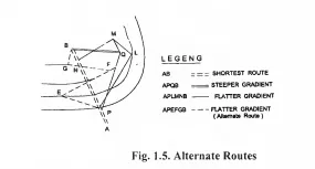
(vi) When the road passes through hilly or mountainous terrain, additional data regarding the geological formation, type of rocks, dip of strata, seepage flow, etc. may be observed so as to decide the stable and unstable sides of the hill for road alignment. From the details collected during the reconnaissance, a few alternate alignments may be chosen for further studies that are based on the practical considerations observed at the site. Preparation of alternate routes is shown in Fig. 1 .5. A suggested composition of the team and equipments required to be available for efficient and effective conduct of the ground survey is given in IRC:SP:48 “Hill Road Manual”.
Preliminary survey : The mam objectives of the preliminary survey are:
(i) To survey the various alternative alignments proposed after the reconnaissance and to collect all the necessary details of topography, drainage and soil.
(ii) To compare the different proposals in view of the requirements of a good alignment.
(iii) To estimate the quantity of earthwork, materials and other construction aspects and to work out the tentative costs of alternate alignments.
(iv) To finalise the best alignment from all considerations.
The survey consists of establishing a base-line traverse, which is a series of straight lines along the selected alignment. The preliminary survey can be carried out using suitable survey equipments, such as, theodolite, etc. depending on the degree of reliability and accuracy required. However, a plane table survey would be sufficient in most cases where other equipments may not be available. Levels should be taken along the traverse and across it. Levels along the centre line should be taken at intervals of 50 m and at all intermediate breaks in ground. The cross-sections should be taken at intervals of 100-250 m in plain terrain, upto 50 m in rolling terrain, and upto 30 m in hilly terrain. The benchmarks shall be established at intervals of 250 to 500 metres. Physical features, such as, buildings, trees, monuments, utilities, railway lines, canals, drainage channels should be located by means of offsets. While the traverse is being run, apart from the general information about traffic, hydrological data may be collected so as to estimate the type, number and approximate size of cross drainage structures. The soil survey data should be collected for working out the details of earthwork, slopes and suitability of materials. The data regarding subsoil and surface drainage requirements, pavement type and approximate thickness requirements should be collected during the preliminary survey. At critical locations, like, sharp curves, hair-pin bends, bridge crossings, etc. the plans should also show contours at 1 to 3 m intervals, particularly for roads in rolling or hilly terrain so as to facilitate the final decision. Aerial photographic survey, in case of hilly areas is very much suited for preliminary survey when the distance and area to be covered are vast or the terrain is not hospitable to physical survey.
Determination of final centre line :
Making use of the maps from preliminary survey showing the longitudinal profile, cross-sections and contours, a few alternative alignments for the final centre line of the road are drawn and studied and the best one satisfying the engineering, aesthetic and economic requirements is selected. Horizontal curves are designed and the final centre line is marked on the map. The vertical curves are designed and the profile is then determined.
Final location and detailed survey :
The alignment finalised after the preliminary surveys is to be translated on the ground by establishing the centre line. The line to be established in the field should follow as closely as practicable the line finalised after the preliminary survey and conforming to the major and minor control points established and the geometric design standards. However, modifications in the final location may be made in the field if necessary. A compass survey may be sufficient in normal course. The centre line may be stacked at 50 m intervals in straight reaches and 25 m intervals on curves. In hilly and mountainous reaches, the interval may be reduced to 20 m and 10 m respectively. The points of transit and intersection should be properly marked and referenced. Temporary benchmarks shall be fixed at intervals of about 300 m. The levelling work is of great importance as the vertical alignment (especially in hilly areas), earthwork calculations and drainage details are to be worked from the levels noted. Normally, the earthwork computations are based on centre line levels in case of plain country. The cross-section levels may be taken upto the desired width at intervals of 30 m or at closer intervals where there are abrupt changes of slopes. All river crossings, valleys should be surveyed in detail upto considerably greater distances on either side. A detailed soil survey shall be carried out to enable drawing of the soil profile. The depth upto which the sampling is to be done may be 1 .50 to 3.0 m below the ground line or finished grade of the road whichever is lower. The data collected during the detailed survey should be elaborate and complete for preparing detailed plans and estimate of the project.


Comments are closed