The primary purpose of a road drainage system is to remove the water from the road and its surroundings. The road drainage system consists of two parts: dewatering and drainage. “Dewatering” means the removal of rainwater from the surface of the road. “Drainage” on the other hand covers all the different infrastructural elements to keep the road structure dry. In Sweden “dewatering” is further divided into two parts: runoff (“avrinning”) and dewatering (“avvattning”). “Runoff” covers the water flowing from the surface of the pavement via road shoulders and inner slopes to the ditches. “Dewatering” covers the collection and transport of water from the surface and structure of the road so that there will be no ponds on the road or in the ditches.

“Dewatering” consists of following elements:
– Cross fall
– Road shoulders
– Impermeable road surface materials
A typical “drainage” system consists of following elements:
– Outlet ditches
– Side ditches
– Culverts
– Inner/outer slopes
– Road structures
– Underdrains
The general score of road drainage system is dependent on its “weakest link”. This means that if any of its elements is out of order, the whole system will not operate as planned and the road will be damaged. On the other hand a well built and maintained road drainage system is a very sustainable investment policy. The main advantages of a good drainage system are: effective removal of rainwater out of the road surface and its surroundings, road structures that stay dry, good bearing capacity, and a road that is nice and safe to drive.
Pavement and wearing course
The pavement or wearing course is the top layer of a road. One function for the pavement is to provide a waterproof covering for the lower pavement structure. This can be achieved if the pavement is impermeable and has no cracks. The topmost wearing course must also have an adequate cross fall to lead water (from rain, melting snow or ice) immediately away from the road surface.

The recommended cross fall will depend on the road type and on the material of the topmost layer. On a straight road cross fall will range between 3 and 5 %. On asphalt the recommended cross fall is 3 %, and for gravel roads it is 5%. On a straight road cross fall is normally applied as a crown section.

On curves, cross fall is applied in the form of superelevation, also called “one-sided cross fall”. Also, on narrow roads, it is difficult to create and maintain a crown section due to the available width. So for low volume gravel roads it is usually more effective to implement full cross fall (in-sloped or out-sloped road) rather than a crown. The minimum requirements for cross fall on curves have to be determined on a case by case basis. The cross fall will depend for example on the speed limit and the geometry (curve radius) of the road. The cross fall of curves is important also for driving dynamics.

A very important issue with cross fall is that it should not have major changes in short distances as this can cause warping problems for high and heavy trucks as well as traffic safety hazards. The importance of proper cross fall is discussed in greater detail in the ROADEX reports on human body vibrations by Johan Granlund


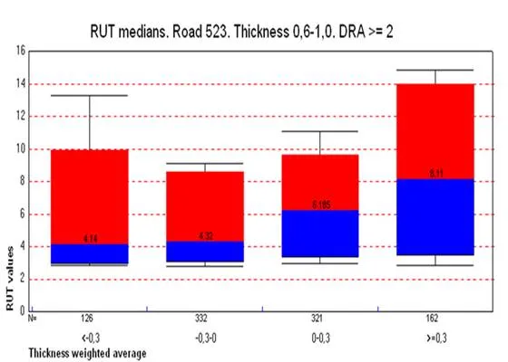
Crossfalls have been quite difficult and expensive to measure in detail from a moving car in the past but recently profilometers, 3D accelerometers and laser scanner techniques have provided new tools to measure cross fall more effectively. Test results with these techniques have also given also very interesting information on the importance of drainage to cross fall and vice versa.


Side ditches
Side ditches collect road water and lead it onward to outlet ditches and are especially important when road is in cut. If the road is on a high embankment, side ditches are not always necessary and their need has to be evaluated case by case.


The longitudinal gradient of side ditch should be at least 4 ‰ (4 mm/m) according to old Finnish guidelines, and in Sweden the longitudinal gradient should be at least 5‰ (5mm/m).


In Sweden side ditches are classified into two categories: 1) road cut ditches (“skärningsdike”) and 2) rainwater ditches (“dagsvattendike”). According to Swedish guidelines the depth of the side ditch (“skärnings dike”) should be at least 30 cm below the bottom of the pavement structure. The same minimum depth in Finland is 25cm. Norway has the highest requirements of 35 cm on a newly constructed road. Deeper side ditches than these values do not significantly improve drainage. ROADEX tests in Sweden have confirmed these recommendations are valid.


A rainwater ditch means that the ditch only collects rainwater from the road and its surroundings, i.e. the surface soil is dry and the groundwater table is deep. In Sweden the design depth of this type of ditch is 0.5m measured from the road surface. This ditch type can be used where the sub grade is water permeable and the groundwater table is deeper than 1.0m below the lower surface of the road. According to old Finnish road design guidelines the depth of this ditch type (rainwater ditch) should be 15 cm below the pavement structure bottom. Additionally the sub grade should be non-frost-susceptible.

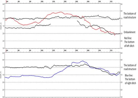
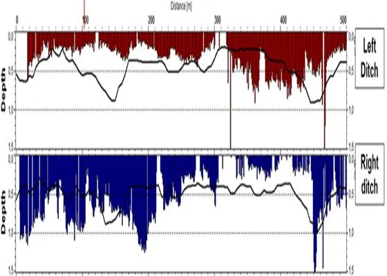
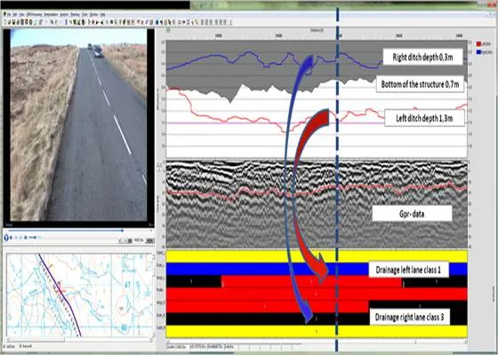
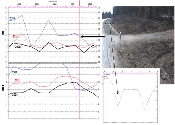
The condition of ditches has traditionally been evaluated visually, but the method is accepted to be subjective and sensitive to the time when the evaluation was made. Additionally the shape of ditches usually change very slowly with the result that only the worst spots are detected visually, and the ditch bottom is usually unseen. The ROADEX project has tested a number of techniques to resolve these difficulties and the best results were achieved using a combination of laser scanners and GPR techniques.
Outlet ditches
Outlet ditches are drainage structures that lead the water from the side ditches away from the road area. The water from outlet ditches normally discharges to existing waterway systems, such as river channels and lakes. The outlet ditch is a critical part of road drainage system but often ignored. If the outlet is clogged, it can create significant problems to the road over a large area. Outlet ditches are normally located outside the road area with the result that the road administrator may not always own the land that they pass through. This can create difficulties in gaining permissions from the landowner when the outlet ditch is clogged and requires re-opening.
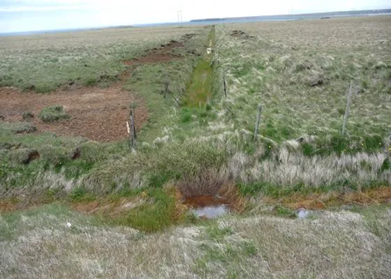
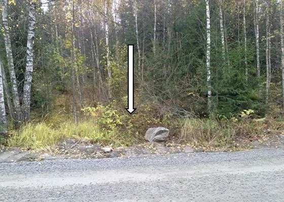
It is recommended that the longitudinal gradient of an outlet ditch should be at least 4‰. In practice this may require to be reduced to a lower gradient to suit the local circumstances.
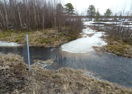
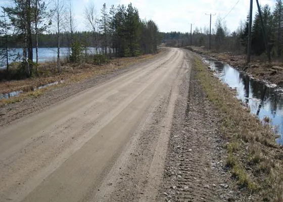
Outlet ditches should be excavated in such as fashion to discharge into a natural watercourse at the same level as the bottom of the natural channel. If there is no natural channel, the outlet ditch should be excavated for a suitable distance to minimize any accumulations of silt, mud or other harmful materials.
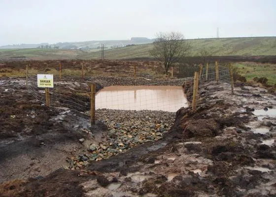
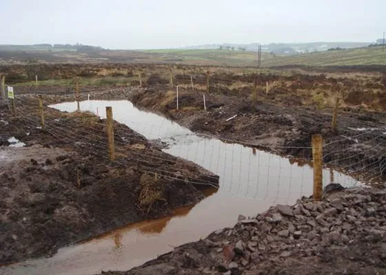
The location and evaluation of outlet ditches has always been a challenge in an drainage inventory. This is especially the case in drainage surveys from a moving vehicle and ROADEX has tested different techniques to resolve assess the most suitable method. The best option was found to be the use of a video camera installed at a 90o angle to the survey van to record the condition of the ditches. GPS data with z-coordinate information can help to identify likely places for outlet ditches as they are most often on the lowest point of a valley.

Main road culverts
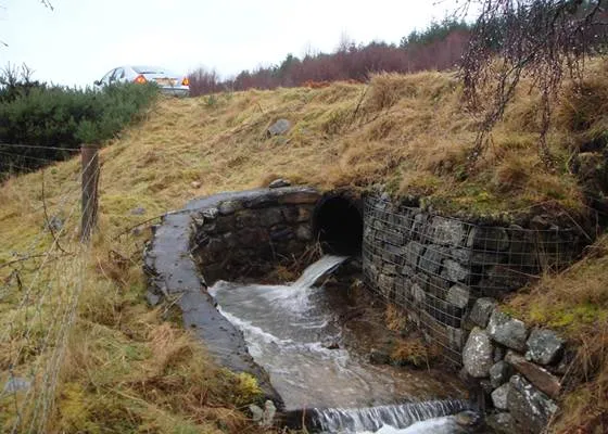
A culvert is a pipe or box structure generally used as cross drains for ditch relief and to pass water under a road at natural drainage and stream crossings. In Finland a culvert is defined to be a culvert if its clear opening is less than 2m, if it is more than 2m it is defined as a bridge. If the construction is a large pipe with a clear opening of 2-4 m, the culvert is defined as a pipe bridge. The shape of a culvert is usually a round pipe, but culverts can also be pipe arch, structural arch or box. The shape depends on the site, the required area and the allowable height of soil cover.
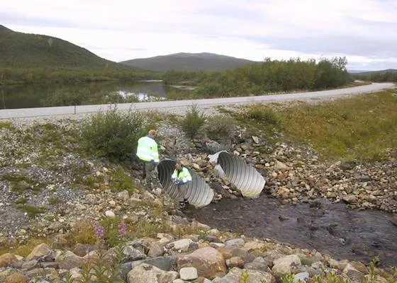
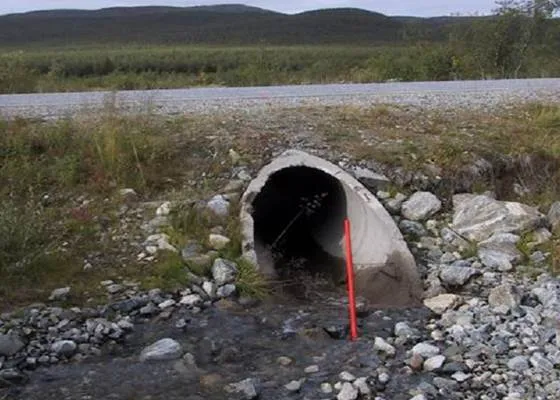
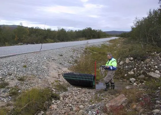
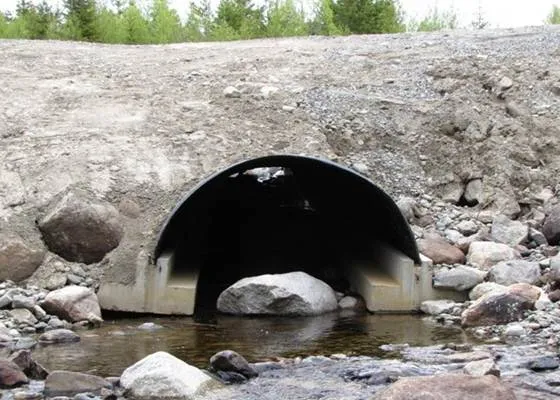
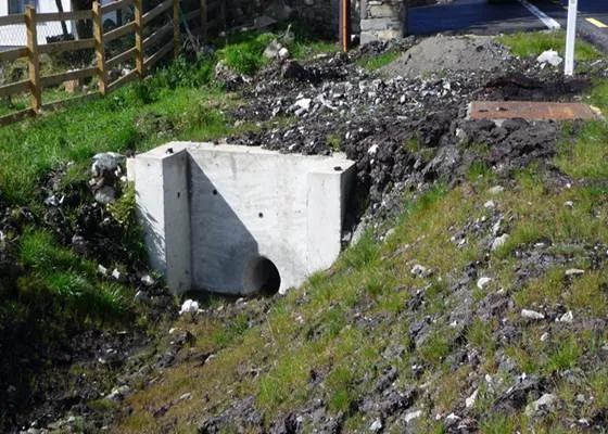
Culverts can usually be obtained as plastic, steel or concrete. Some old culverts can also be made of wood or masonry. Plastic culverts are often easier to maintain than culverts made of other materials as ice does not bond so easily to their plastic surfaces.
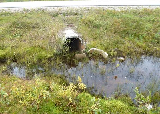
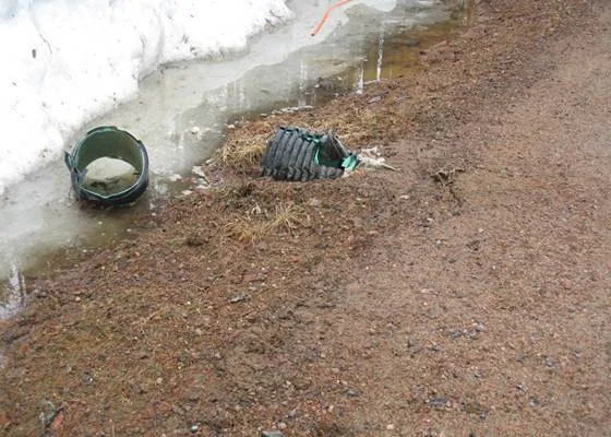
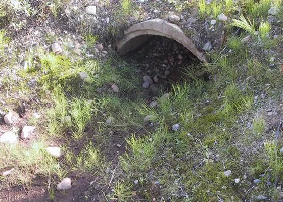
Culverts pipes are expensive, and the relatively small culvert pipes used for cross-drains can be susceptible to clogging and require cleaning. That is why, when planning the installation of a culvert, the most important thing to keep in mind is to make sure that the culvert is adequately sized and has overflow protection. Culverts should also be installed in accordance with the manufacturer’s instructions and suitably protected from erosion, scour and road maintenance equipment.
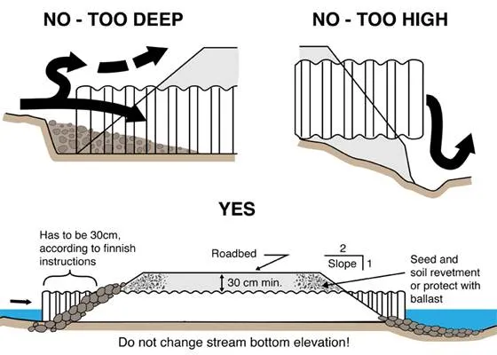
Main road culverts should be installed in the lowest point of the terrain. The rule of thumb when installing a culvert is that natural channel modifications should be minimized and that any constriction of the channel flow width must be avoided. This can be done by maintaining the natural grade and alignment of the channel through the culvert.
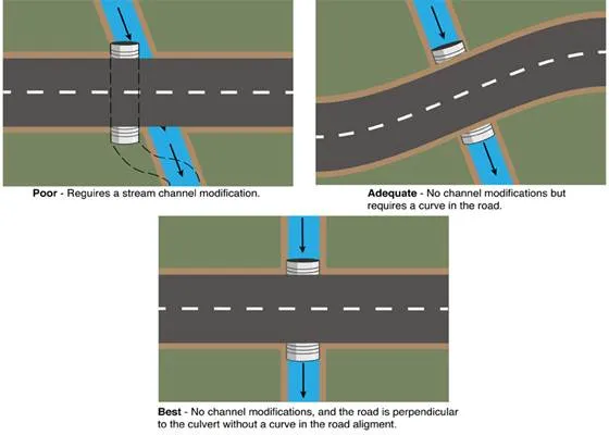
The height and position of a culvert will be dependent on a number of matters:
– An adequate longitudinal gradient (at least 1% to prevent the accumulation of silt or mud)
– The depth of the side ditch
– The level of the drainage system in the surrounding terrain
– It should be also kept in mind that many times, in weak soil areas, the road will settle around the culvert which will cause ditch bottom level to rise.
Culverts should normally be installed orthogonally to the road alignment. They can also be installed at an angle to the road alignment if required by local circumstances.
Materials for the foundation and backfill, as well as material for transition wedges, should be non-frost susceptible and should not contain rocks larger than 75mm. The foundation material should not contain rocks larger than 40 mm. A moist, well graded granular or sandy gravel soil with up to 10 % of fines is an ideal backfill material.
In Finland the recommended minimum size for a main road culvert in low volume roads is 400mm (if the length of the culvert is not more than 10m). The “size” of the culvert is defined as the inner diameter of the pipe. There are some exceptions to this rule. For example, installing a new smaller pipe inside an old pipe, when it is known that the old culvert has been too large. Ideally, the width of a culvert should be as wide as the natural channel to avoid channel constriction.
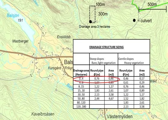
| DRAINAGE STRUCTURE SIZING | ||||
| Steep slopes Bare, light vegetation | Gentle slopes Heavy vegetation | |||
| Drainage area (Hectares) | Round pipe Ø (m) | Area (m2) | Round pipe Ø (m) | Area (m2) |
| 0..4 | 0.76 | 0.46 | 0.46 | 0.17 |
| 4..8 | 1.07 | 0.89 | 0.61 | 0.29 |
| 8..15 | 1.22 | 1.17 | 0.76 | 0.46 |
| 15..30 | 1.83 | 2.61 | 1.07 | 0.89 |
| 30..50 | 2.13 | 3.58 | 1.22 | 1.17 |
| 50..80 | 2.44 | 4.67 | 1.52 | 1.82 |
| 80..120 | 1.83 | 2.61 | ||
| 120..180 | 2.13 | 3.58 |
When designing the size of culvert a number of matters should be taken into account, i.e. size of drainage area, surrounding terrain type, rainfall intensity, etc. The table below gives some examples of different sizes of culverts. The table is modified after Geller & Sherad: “Low volume roads engineering – Culvert use, installation and sizing”. Rainfall intensity has been assumed to be 75 – 100 mm/h. The situation of bare land with light vegetation and steep slopes has a higher runoff coefficient than forest land with heavy vegetation terrain and gentle slopes. For an intermediate terrain the pipe size can be interpolated. If the suggested pipe size is not available, the next larger pipe size should be used.
The outlet of a culvert pipe should ideally be located in a stable, non-erosive area. Well-vegetated or rocky areas are good places to locate a culvert. Water flowing from a culvert can cause erosion problems where it discharges directly on to erosive soil. Channel protection, riprap or other structural solutions are not as good as a correctly sized and well placed pipe.
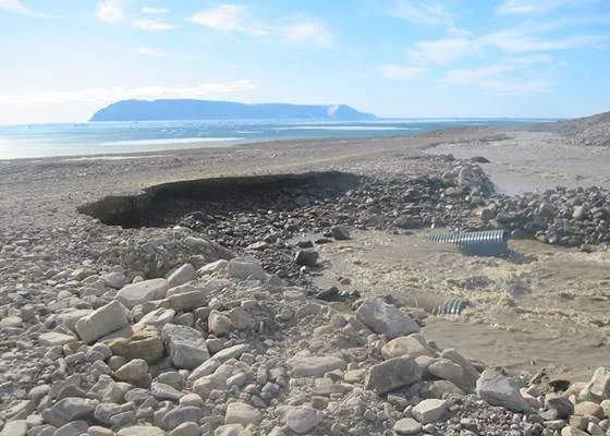
Access road culverts
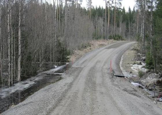
Access road culverts permit the water in side ditches of main roads to pass through side roads joining the main road. Such roads can be main road intersections or simple private access roads. The function of the access road culverts is to provide a continuation of the main road ditch through the side road as if the road did not exist.
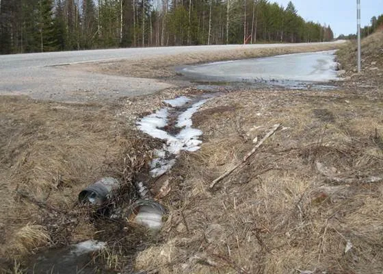

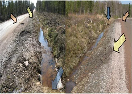
According to old Finnish guidelines the minimum size of exit road culvert should be 400mm when the length of culvert is more than 8m. If the length is less than 8m, the minimum size can be 300mm. The length of the culvert will depend on the width of the access road and is often large where there are shops, petrol stations and other businesses. Access road culverts have historically had a smaller diameter than main road culverts and the water also has a lower flow velocity. These smaller diameter culverts can clog and cause water to infiltrate into the layers of the main road and weaken them, or cause severe erosion problems.
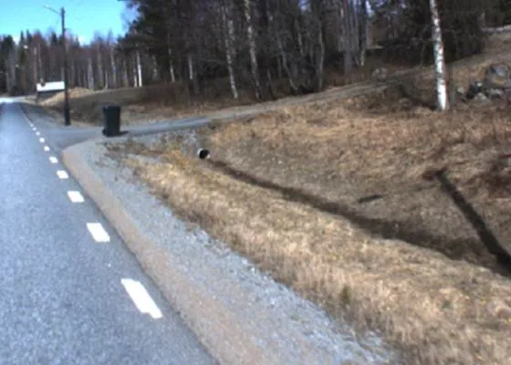
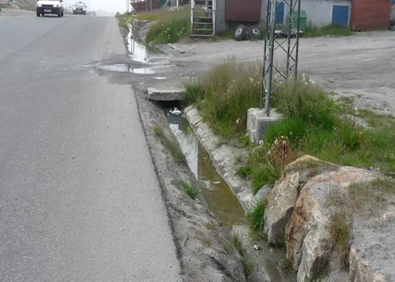
The responsibility of the maintenance of access road culvert varies across the ROADEX partner countries.
In Finland the owner is often a private person and the maintenance responsibility of the culvert belongs to the owner of the access road. This can cause problems as often these private persons neglect their responsibility for keeping the culvert clean. Quite often the culverts are also too small or built incorrectly. This creates problems to the road drainage and leads to damages in the main road. In Sweden the owner of access road culvert is the road administrator (Trafikverket) and the responsibility for maintenance belongs to them. In Scotland too, the responsibility for the maintenance of access road culverts falls on the road authority (i.e. the local Council for low volume roads, and Transport Scotland for the national roads). In Norway the ruling is similar to Sweden. In Norway, the Norwegian Public Road Administration owns 3 metres from the edge of the road. Most of the access road culverts lie in this area and so the NPRA is responsible for them.
In Iceland private landowners have to pay all costs concerning their access road culverts. Culverts have to be constructed according to ICERA guidelines. The maintenance of access road culvert is the responsibility of ICERA. ICERA owns 20 metros of land on both sides of the road from the centre line. In Greenland the private landowner builds the access road culvert, but the municipality then takes responsibility for its maintenance.
Road drainage structures & layers
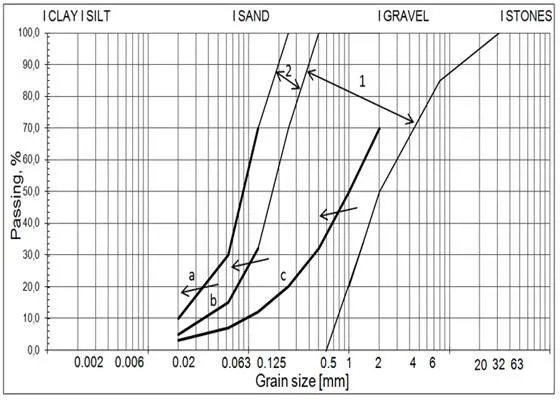
Horizontal road drainage structures include structures such as filter courses, special geotextiles, and special asphalt mixtures (like porous asphalt) that lead the water away from the road, or cut the capillary rise connection from the sub grade to the upper part of the pavement structure. The main purpose of the filter course in road drainage is to cut the capillary rise to the road structural courses above of it. Filter course material should be well graded with a maximum grain size of 31.5mm and should be non-frost-susceptible The thickness of filter courses varies across the Nordic countries from 0.4m to 0.6m thick. The filter course is the lowermost structural layer and is normally spread across the bottom of the excavation. A filter course should always be used in the road structure when the sub grade is frost-susceptible (like clay, silt and silty moraine). The filter course is normally separated from the sub grade soil by a geotextile.
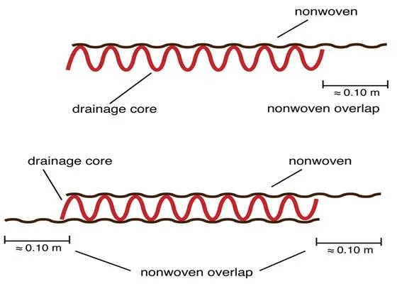
Geotextile composites can also be used as drainage layers. An “Underdrain carpet” is like a sandwich structure that conveys water with the help of its cellular core structure. A plastic rigid core is sandwiched between geotextiles. The carpet is laid out on even ground and covered with a layer of aggregates that is thick enough thick to protect the carpet from the action of heavy vehicle loads.
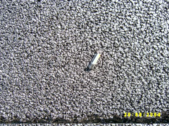
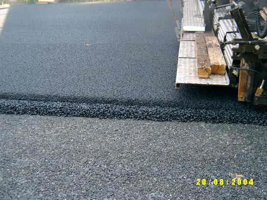
Porous asphalt is used in countries suffering from large amounts of rainfall. This special asphalt mix ensures a fast drainage of water away from the pavement surface. This reduces the risk of hydroplaning and bad visibility conditions due to “splash and spray”, and improves overall road safety. Water does not easily collect on a porous asphalt surface during the heavy rains as the majority of the stones in the mixture are of a similar size (i.e a very steep grading curve). The thickness of a porous asphalt layer is typically 20-100mm and it is placed on top of an impermeable asphaltic base. Although the material is good in wet conditions, it has a few disadvantages. It has a lack of durability and it has to be ensured that there is enough bitumen to coat the stones. If there is too much bitumen, the mixture will rut easily and the pores will block with bitumen. If there is too little bitumen, raveling will occur. Porous asphalt can become clogged and lose its efficiency with the ingress of particulates and dust from the environment, blown soil, engine wear and cargoes. Snow, ice and de-icing salts in winter can also clog the pores and prevent the flow of water.
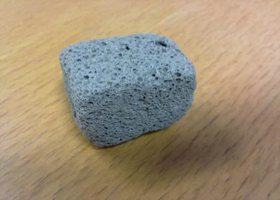
Finally, special materials such as foamed recycled glass have been used as drainage and frost insulation layers. Wood bark has also been used In forest roads.
Vertical drainage structures, underdrains
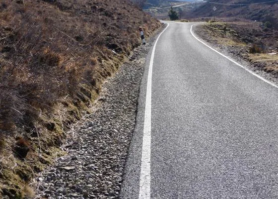
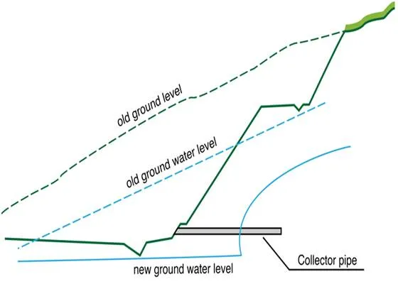
Vertical subsurface drainage structures are commonly used along roads in wet areas, for example in a wet cut bank with seepage. The purpose of these vertical drainage structures is to remove the groundwater and keep the sub grade dry under the road. Vertical subsurface drains can be divided in two main groups; 1) interceptor drains and 2) water table lowering drains.
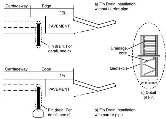
It can sometimes be more cost effective to use vertical drainage structures than adding a thick structural section to the road, or making frequent road repairs. This is the case especially with high volume roads. A typical under drain comprises an interceptor trench (depth of 1-2 metres) and a backfill. The drains are usually filled with a highly permeable material, wrapped in a geotextile, with a perforated tube or permeable material near the bottom. Geo-composite based drainage systems, otherwise known as a “fin drain”, are typically only a few centimeters thick. These types of drainage systems are usually placed at the edge of the pavement structure, parallel to the road centerline.
Trench drains (”French” drains)
A trench drain consists of a drain wrapped in a geotextile. It is made of round or crushed aggregate. In earlier years the drain was installed without a pipe in its base but currently some form of carrier drain pipe is usually included. The geotextile wrapping fabric is provided to prevent migration of fine soil particles into the drain and clogging it. The geotextile should be water permeable allowing water to flow freely from the surrounding ground into the drain.
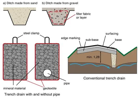
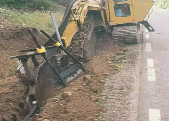
A step by step-example of how to make the Trench drain:
1. Excavate a narrow trench
2. Clean out the excavated trench
3. Line the surfaces of the excavation with a geotextile
4. Place a layer of aggregates in the bottom of the lined trench
5. Install a carrier pipe if needed
6. Fill the drain with aggregates
7. Close the drain and wrap over the geotextile (minimum overlap is 30cm)
8. Cover the closed drain surface with at least 3-5cm of top soil or other low permeability material. If surface runoff is to be collected also the covering material should be permeable.
Fin drains are longitudinal drains, manufactured from composite materials. A fin drain usually comprises two geotextiles outer faces, to provide a filter function with the surrounding soil, and a rigid plastic core that is sandwiched between geotextiles. A fin drain can also feed into an integral collector at the bottom of the drain. Water flows through the geotextile facings into the core that then transports the water to an outlet ditch.
Inner and outer slope drainage structures
The goal in designing the inner and outer slopes on a road is to use as gentle slopes as possible. Gentle slopes are friendlier for the environment, are better for traffic safety and have a higher resistance against erosion. The inclination of a typical slope will depend on the road category (rural road, main road, motorway etc.) and the local topography. The recommended inclination for an inner slope on a main road according to old Finnish guidelines is a minimum of 1:2 and for outer slopes a minimum of 1:4
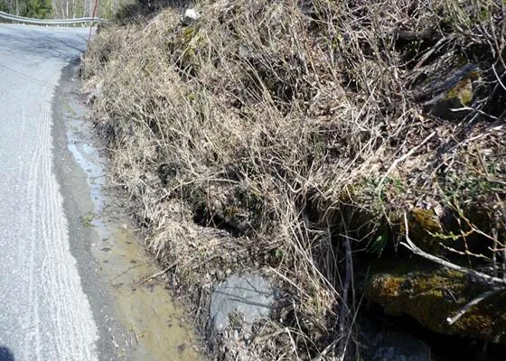
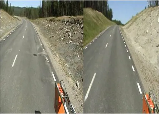
Poor slope stability can cause problems to the drainage of a road and result in road damages. Material flowing to the bottom of a ditch can block the water flow in the ditch and lead to water infiltrating into the road structures. This can then lead to differential frost heave and shoulder deformation. ROADEX research has shown that unstable slopes are one of the main reasons for road failures in test roads in Finland.
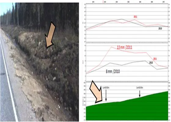
A special problem that has found to cause problems is that water susceptible material from the ditch bottom has been placed back to inner slope during the ditch cleaning. This material is then flowing quickly back to the ditch bottom and leading to further problems with the road.
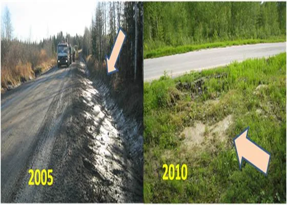
Special drainage structures
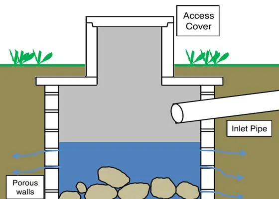
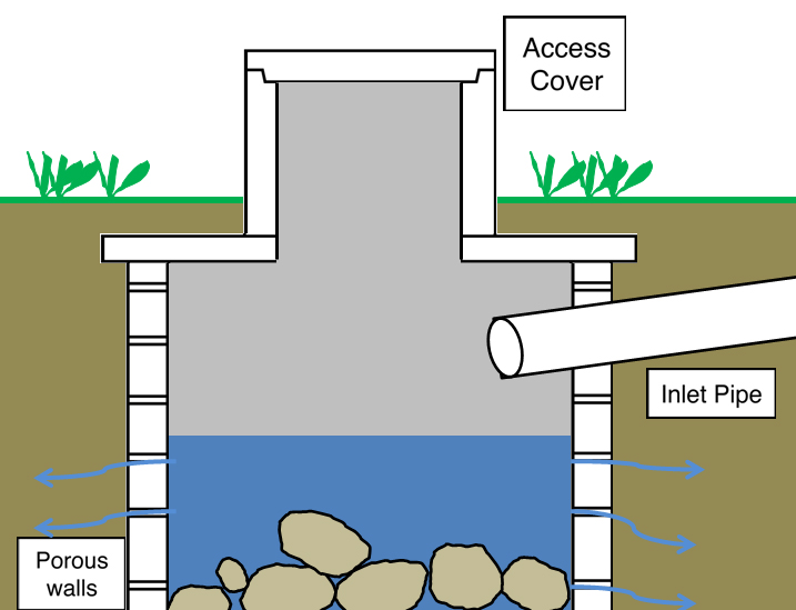
Once water has been collected from a road and its surroundings it has to be led out of the road area to an acceptable discharge point. Usually this is a natural water system such as a river, lake or channel. If this is not possible, one solution can be the use of a “soakaway”. The purpose of a soakaway is to dispose of water back into the natural circulation from where it came, i.e. water seepage back to nature via porous walls. Soakaways can only be used in porous subgrades and not, for example, in clay areas. Soakaways have to be individually designed for size and capacity. The finished soakaway space must be kept open and free from clogging to remain effective.
Comments are closed