INTRODUCTION
Building a roadway is like building any other structure. You must begin with a firm foundation to end up with a quality job. Many structural problems associated with our roads can be traced back to an improper foundation. Overall performance of a pavement structure ultimately depends upon the proper construction of the following three elements:
§ Foundation
§ Subgrade
§ Embankment
FOUNDATION CONSTRUCTION
To prepare for construction of an embankment:
§ Establish erosion controls
§ Clear and grub
§ Start with a firm foundation
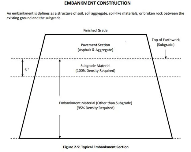
Before excavation and filling begin, we must ensure that a firm foundation is provided on which to build the embankment. During embankment construction, following proper methods and construction practices ensure we produce a structurally competent element to support our roadway as well as it’s own weight. Additionally, after our embankment is finished, we must provide a firm foundation for our pavement structure. The foundation in this case is the subgrade, which is the top of the shaped earthwork.
Often, the pavement structure itself is more closely scrutinized and more heavily monitored than the three elements outlined above. However, the best materials and construction will not make up for lack of quality of foundation, embankment and subgrade. Competent testing and monitoring during construction is a key factor in achieving a quality product and should be of primary concern to the Construction Inspection team. This chapter is intended to give the student a working knowledge of the construction of embankments and subgrade including specifications, documentation, and standard methods and practices.
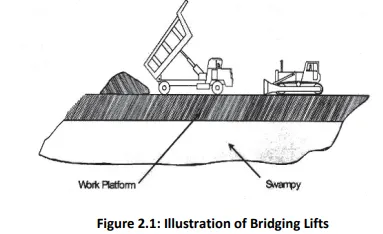
WORK PLATFORM CONSTRUCTION FOR SOFT/YIELDING AREAS
Two techniques used to construct work platforms are bridging lifts and geosynthetic fabric. Figure 2.1 illustrates common practice for “bridging” over swampy areas to construct a “work platform” for the remainder of the embankment. The thickness of the “bridging” layer should be such that it is capable of supporting hauling equipment while subsequent layers are being placed. An alternative method of creating a work platform is the use of geosynthetics to separate and reinforce the bridge layer placed on the swampy/soft area or later reinterpretation. In addition, plans and specifications need to define the responsibilities of both department and contractor.
The nose, or leading edge, of the embankment should be maintained in a wedge shape to facilitate mud displacement in a manner that will prevent its being trapped in the embankment. The front slope of the wedge should be maintained at a slope ratio steeper than 2H:1V. Compaction equipment should not be used on this platform layer. To reduce the thickness of the work platform and possibly its impact on the swampy area by mud displacement, a geosynthetic can be placed on the swamp prior to the placement of the material that will be used to construct the work platform. Again compaction equipment should not be used on this material. Regardless of how the work platform is constructed any subsequent layer should be compacted as required in the specifications. Special situations may arise such as the presence of underground tanks, existing foundations and slabs located within the construction limits. These structures must be removed and disposed of in a location approved by the Engineer. In lieu of removal, foundations and slabs located 3 feet or more below the proposed subgrade may be broken into pieces not more than half a foot in any dimension and reoriented to break the shear plane and allow for drainage. Tanks may be filled with flowable fill.
EROSION AND SILTATION CONTROL:
Erosion and siltation controls must be installed prior to beginning any land disturbance. Silt fence, filter barrier, baled straw, check dams, or brush barriers are needed to protect surrounding land and waterways from the effects of erosion and siltation. The most commonly used erosion and siltation control devices are temporary silt fences and fabric silt barriers. Baled straw silt barriers may be substituted for silt fence with the approval of the Engineer in non‐critical areas, such as pavement locations where filter barriers cannot be installed as shown on the plans or required by the specifications, locations where the runoff velocity is low, and locations where the Engineer determines that streams and other water beds will not be affected. Silt sediment basins are required if rain runoff from a watershed area of 3 acres or more flows across a disturbed area. Erosion and siltation control devices and measures shall be maintained in a functional condition at all times. The Contractor shall have on the project site an employee certified in Erosion and Sediment Control and designated as the RLD (Responsible Land Disturber). The RLD certification it is to be obtained from the Department of Environmental Quality. The RLD shall inspect temporary and permanent erosion and siltation control measures for proper installation and deficiencies immediately after each rainfall, at least daily during periods of prolonged rainfall, and weekly when no rainfall occurs. Deficiencies shall be immediately corrected. The Contractor shall make a daily review of the location of silt fences and filter barriers to ensure that they are properly located for effectiveness. Where deficiencies exist, corrections shall be made immediately as approved or directed by the Engineer. The absence of the RLD will result in suspension of any land disturbing activity.
CLEARING AND GRUBBING
Clearing is defined as the removal of trees, brush, debris, and other large items, while grubbing is the removal of stumps, roots, and topsoil. Clearing and grubbing should not apply to vegetation and objects that are designated to be preserved, protected, or removed in accordance with the requirements of other provisions of the specifications. Grubbing of rootmat and stumps shall be confined to the area where excavation shall be performed within 15 days following grubbing. When and Where to Clear and Grub Clearing and grubbing is required in these areas:
§ All cut sections
§ Fill sections less than 5 feet in depth and directly beneath the pavement and shoulders
§ Any borrow excavation sites
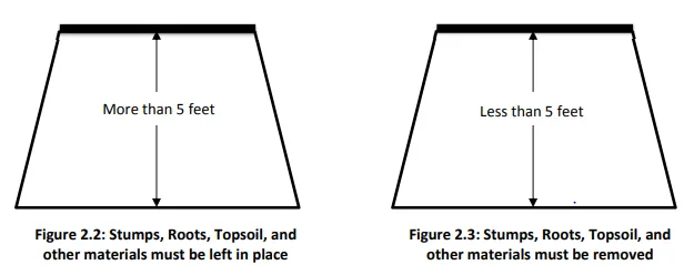
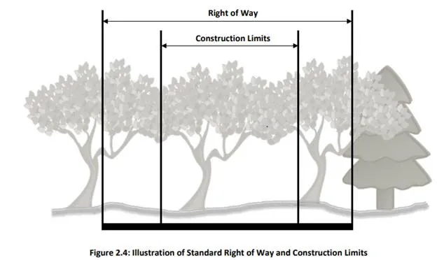
Clearing is required in all areas within the construction limits or designated on the plans. The Contractor may clear and grub to accommodate construction equipment within the right of way up to 5 feet beyond the construction limits at his own expense, if approved by the Engineer. Erosion and siltation control devices shall be installed by the Contractor prior to beginning grubbing operations.
The surface area of earth material exposed by grubbing, stripping topsoil, or excavating shall be limited to that necessary to perform the next operation within a given area. Grubbing of root mat and stumps shall be confined to the area over which excavation is to be performed within 15 days following grubbing.
Any stumps left in place must be no more than 6” above original ground, or low water level. Branches of trees that overhang the roadway or reduce sight distance and that are less than 20 feet above the elevation of the finished grade shall be trimmed using approved tree surgery practices. Vegetation, structures, or other items outside the construction limits shall not be damaged. Trees and shrubs in ungraded areas shall not be cut without the approval of the Engineer. Clearing and grubbing is done in the designated areas of the fill section to ensure that organic matter is not a factor in the structural integrity of the embankment foundation. The surface area directly beneath the pavement and shoulders, on which embankments of less than 5 feet in depth are to be constructed, shall be grubbed. Areas that will support compaction equipment shall be scarified and compacted to a depth of 6” to the same degree as the material to be placed thereon When the material to be excavated makes the use of explosives necessary, the Contractor needs to notify each property and utility owner having a building, structure, or other installation above or below ground in proximity to the site of the work where they intend to use explosives. The specifications detail the Contractor’s responsibility and necessary actions to be taken. Where rock or boulders are encountered, the Contractor needs to excavate and backfill by specified methods of undercutting rock.
Disposal of Removed Material
Combustible cleared and grubbed material shall be disposed of in accordance with the following:
§ Used in Erosion Control Systems
§ Buried as directed by the Engineer
§ Burned if allowed by local ordinance
When specified on the plans or where directed by the Engineer, material less than 3 inches in diameter shall be used to form brush silt barriers when located within 500 feet of the source of such material. Material shall be placed approximately 5 feet beyond the toe of fill in a strip approximately 10 feet wide to form a continuous barrier on the downhill side of fills. Where selective clearing has been done, material shall be piled, for stability, against trees in the proper location. On the uphill side of fills, brush shall be stacked against fills at approximately 100 foot intervals in piles approximately 5 feet high and 10 feet wide. Any such material not needed to form silt barriers shall be processed into chips having a thickness of not more than 1/3 inch and an area of not more than 6 square inches and may be stockpiled out of sight of any public highway for use as mulch. Stumps and material less than 3 inches in diameter that are not needed to form silt barriers and that are not processed into wood chips shall be buried where designated on the plans and permitted by the Engineer, placed in disposal or borrow pits, or disposed of by burning in accordance with the requirements of Section 107.16(b)2. Trees, limbs, and other timber having a diameter of 3 inches and greater shall be disposed of as saw logs, pulpwood, firewood, or other usable material; however, treated timber shall not be disposed of as firewood. Not more than 3 feet of trunk shall be left attached to grubbed stumps.
When specified that trees or other timber is to be reserved for the property owner, such material shall be cut in the lengths specified and piled where designated, either within the limits of the right of way or not more than 100 feet from the right‐of‐way line. When not reserved for the property owner, such material shall become the property of the Contractor. Any consideration of marketable use of this material should be cleared with the Engineer.
GRADING METHODS AND PRACTICES
The following are some of the methods and practices used to protect the work, however the department reserves the right to require the contractor to use other temporary measures not discussed here or in the specifications to protect erosion or siltation conditions.
Grade to Drain
§ Crown Surface
§ Roll Surface
§ Direct Water
§ Install Slope Drains
§ Install Side Ditches.
Unless precautions are taken, rainfall can be a hindrance during construction. The top of earthwork shall be shaped to permit runoff of rainwater. Temporary earth berms should be constructed and compacted along the top edges of embankments to intercept run off water. Temporary slope drains should be included to intercept and transport the runoff water to prevent damage to the earth slopes by erosion. These drains may be of flexible or rigid material. The contractor can also lessen the impact of erosion by maintaining the specifications suggested schedule for seeding slopes. The practices outlined above will help the contractor get back to work sooner than if they had not been followed, but they are not a cure‐all for wet weather. After a rain the surface of the embankment or subgrade in cut sections should be checked for acceptable moisture content. When the moisture in the upper part of the embankment or subgrade is too wet, measures must be taken to ensure that otherwise acceptable material is not placed on top of wet material. Methods for handling adverse moisture conditions will be discussed in a later section. If drainage structures are involved in the work, the construction of check dams and silt settlement boxes should be one of the initial items of work accomplished.
After necessary clearing and grubbing and once a firm foundation is obtained, embankment construction can begin. Failure to do this can result in compaction problems throughout it’s construction. As discussed before, the surface area directly beneath the pavement and shoulders on which embankments of less than 5 feet in depth are to be constructed shall be denuded of vegetation. Areas that will support compaction equipment shall be scarified and compacted to a depth of 6 inches to the same degree as the material to be placed thereon. Soil that is not required to be removed should be thoroughly disked before constructing the embankment. Areas that contain material unsuitable as a foundation for an embankment should be undercut to a firm foundation material and backfilled as directed by the Engineer. Unsuitable material is defined as a material found to be undesirable for use in construction due to its poor load carrying capability, excessive moisture (exceeds allowable moisture content allowed by specifications), organic content, extreme plasticity, or other reasons. Cisterns, septic tanks and other structures have to be filled with broken foundation masonry or rock placed in uniform layers and thoroughly compacted. Wells have to be closed in accordance with Department Policy.
Requirements of Embankment Materials
§ Must be approved material (meet AASHTO M57)
§ Must not contain muck
§ Must not contain frozen material
§ Must not contain roots
§ Must not contain sod
§ Must not contain other deleterious material
Types of Embankment Fills
§ Regular excavation
§ Borrow excavation
§ Commercial sources
§ Specialized materials
Ø Light weight fill
o Aggregate
o Flowable fill
o Cellular concrete fill/foam concrete fill
o Tires
Ø Fly ash
Ø Slag
PLACEMENT OF LAYERS
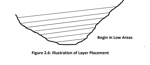
As shown in Fig. 2.6, the first lifts of embankment material should be placed in low areas. Successive layers should be continuously manipulated to provide uniform layers approximately parallel to the finished grade. As material is brought in and spread, large roots and other objectionable materials must be removed and disposed of in an approved manner
Lift Placement
§ Uniform Layers
o Lift Thickness
o Moisture
o Compactive Effort
§ Parallel to Finished Grade
Because of the large amount of soil in an embankment, it is not feasible to blend it so that the entire embankment is homogeneous. We can, however, take steps to ensure we get uniformity. When soil is being hauled to the project from an excavated area (regular excavation or borrow site), it should be dumped on the lift of embankment currently being constructed and worked into place for compaction. This practice not only blends the soil better but also achieves a better bond between the two layers. Figs. 2.7 & 2.8 show the incorrect and the correct method respectively.
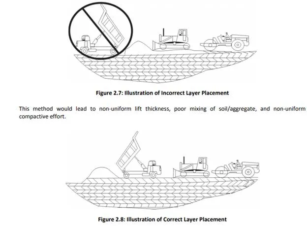
This method promotes uniform layer thickness, improved mixing of soil and/or aggregate in layer, and promotes uniform compactive effort.
Monitoring Lift Thickness
The compaction of soils is influenced by how they are manipulated. Uniform layer or lift thickness is essential in achieving proper compaction. Typical lift thickness for soils in an embankment is eight inches loose, six inches compacted. When lift thickness is increased the actual compaction will decrease for a given compactive effort. As construction progresses, continuous leveling and manipulation of the surface of the fill will help keep the material mixed and the lift thickness uniform. Continual observation in the field is necessary to construct quality embankments. This cannot be overemphasized. Constant maintenance and monitoring of the fill surface helps ensure consistent layer thickness. Lift thickness can be measured as the new lift is placed. Checking the elevation at the top of each lift also ensures that proper lift thickness is maintained. Monitoring lift thickness is a simple procedure when done as a new lift is being placed. Find the leading edge of the new loose lift. Lay a straight edge such as a leveling rod or shovel handle on top of the loose material so that it extends beyond the edge and over the previous compacted lift. Use a rule to measure from the bottom of the straightedge to the top of the previous compacted lift. This provides a good field check of lift thickness.
ROCK FILLS
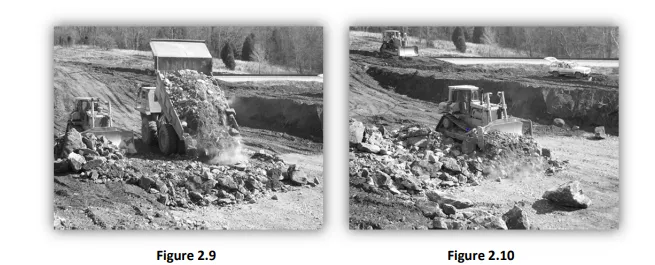
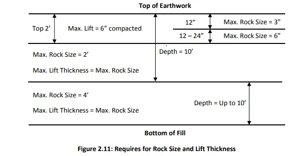
When the excavated material consists predominately of rock fragments of such size that the material cannot be placed in layers of the thickness prescribed without crushing, pulverizing, or further breaking down the pieces resulting from excavation methods, such material may be placed in the embankment in layers not exceeding the thickness of the average size of the larger rocks. Rock not over 4 ft. in its greatest dimension may be placed in an embankment to within 10 ft. of the top of the earth work. The remainder of the embankment to within 2 ft. of the top of the subgrade shall not contain rock more than 2 ft. in its greatest dimension. Each layer shall be constructed so that all rock voids are filled with rock spall, rock fines and earth. Rock shall be placed, manipulated, and compacted in uniform layers. Figures 2.9 and 2.10 show the proper method of spreading rock fill. Rock shall not be end dumped over the edge of the previous layer but dumped on top of the previous layer and worked into place. This reduces segregation of the larger rocks.
The 2 ft. of the embankment immediately below the subgrade shall be composed of material placed in layers of not more than 8 inches before compaction and compacted as specified herein for embankments. Rock more than 3 inches in its greatest dimension shall not be placed within 12 inches of the subgrade in any embankment. Lift thickness and rock size depend on where you are relative to the top of the subgrade. This is illustrated in Figure 2.11.
The best material is to be reserved for finishing and dressing the surface of the embankment. Attention to where and how rock is placed in an embankment is critical to achieving a dense and a stable structure. Moisture shall be added for the purpose of controlling dust. The amount of rock present in an embankment that will preclude conducting density tests should remain flexible and should be at the discretion of the project inspector. It should be understood that if it is possible to conduct a test, then a test should be run.