Hydrostatics
As already mentioned in earlier chapters, the stress distribution in groundwater at rest follows the rules of hydrostatics. More precise it can be stated that in the absence of flow the stresses in the fluid in a porous medium must satisfy the equations of equilibrium in the form
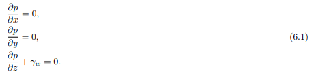
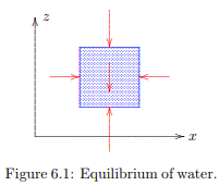
Here it has been assumed that the z-axis is pointing in vertically upward. The quantity γw is the volumetric weight of the water, for which γw ≈ 10 kN/m3 . It has further been assumed that there are no shear stresses in the water. This is usually a very good approximation. Water is a viscous fluid, and shear stresses may occur in it, but only when the fluid is moving, and it has been assumed that the water is at rest. Furthermore, even when the fluid is moving the shear stresses are very small compared to the normal stress, the fluid pressure. The first two equations in (6.1) mean that the pressure in the fluid can not change in horizontal direction. This is a consequence of horizontal equilibrium of a fluid element, see Figure 6.1. Equilibrium in vertical direction requires that the difference of the fluid pressures at the top and bottom of a small element balances the weight of the fluid in the element, i.e. ∆p = −γw∆z. Here ∆z represents the height of the element.
By passing into the limit ∆z → 0 the third equation of the system (6.1) follows. The value of the volumetric weight γw in the last of eqs. (6.1) need not be constant for the equations to be valid. If the volumetric weight is variable the equations are still valid. Such a variable density may be the result of variable salt contents in the water, or variable temperatures. It may even be that the density is discontinuous, for instance, in case of two different fluids, separated by a sharp interface. This may happen for oil and water, or fresh water and salt water. Even in those cases the equations (6.1) correctly express equilibrium of the fluid. In soil mechanics the fluid in the soil usually is water, and it can often be assumed that the groundwater is homogeneous, so that the volumetric weight γw is a constant. In that case the system of equations (6.1) can be integrated to give

where C is an integration constant. Equation (6.2) means that the fluid pressure is completely known if the integration constant C can be found. For this it is necessary, and sufficient, to know the water pressure in a single point. This may be the case if the phreatic surface has been observed at some location. In that point the water pressure p = 0 for a given value of z. The location of the phreatic surface in the soil can be determined from the water level in a ditch or pond, if it known that there is no, or practically no, groundwater flow. In principle the phreatic surface could be determined by digging a hole in the ground, and then wait until the water has come to rest.
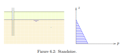
It is much more accurate, and easy, to determine the phreatic surface using an open standpipe, see Figure 6.2. A standpipe is a steel tube, having a diameter of for instance 2.5 cm, with small holes at the bottom, so that the water can rise in the pipe. Such a pipe can easily be installed into the ground, by pressing or eventually by hammering it into the ground. The diameter of the pipe is large enough that capillary effects can be disregarded. After some time, during which the water has to flow from the ground into the pipe, the level of the water in the standpipe indicates the location of the phreatic surface, for the point of the pipe. Because this water level usually is located below ground surface, it can be observed with the naked eye. The simplest method to measure the water level in the standpipe is to drop a small iron or copper weight into the tube, attached to a flexible cord. As soon as the weight touches the water surface, a sound can be heard, especially by holding an ear close to the end of the pipe. Of course, the measurement can also be made by accurate electronic measuring devices. Electronic pore pressure meters measure the pressure in a small cell, by a flexible membrane and a strain gauge, glued onto the membrane. The water presses against the membrane, and the strain gauge measures the small deflection of the membrane. This can be transformed into the value of the pressure if the device has been calibrated before.