Vertical stresses
In many places on earth the soil consists of practically horizontal layers. If such a soil does not carry a local surface load, and if the groundwater is at rest, the vertical stresses can be determined directly from a consideration of vertical equilibrium. The procedure is illustrated in this chapter.
A simple case is a homogeneous layer, completely saturated with water, see Figure 5.1. The pressure in the water is determined by the location of the phreatic surface. This is defined as the plane where the pressure in the groundwater is equal to the atmospheric pressure. If the atmospheric.
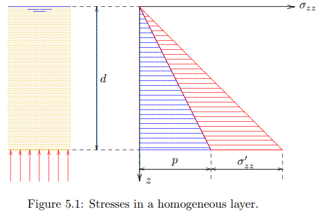
pressure is taken as the zero level of pressures, as is usual, it follows that p = 0 at the phreatic surface. If there are no capillary effects in the soil, this is also the upper boundary of the water, which is denoted as the groundwater table. It is assumed that in the example the phreatic surface coincides with the soil surface, see Figure 5.1. The volumetric weight of the saturated soil is supposed to be γ = 20 kN/m3 . The vertical normal stress in the soil now increases linearly with depth,

This is a consequence of vertical equilibrium of a column of soil of height d. It has been assumed that there are no shear stresses on the vertical planes bounding the column in horizontal direction. That seems to be a reasonable assumption if the terrain is homogeneous and very large, with a single geological history. Often this is assumed, even when there are no data.
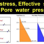
At a depth of 10 m, for instance, the vertical total stress is 200 kN/m2 = 200 kPa. Because the groundwater is at rest, the pressures in the water will be hydrostatic. The soil can be considered to be a container of water of very complex shape, bounded by all the particles, but that is irrelevant for the actual pressure in the water. This means that the pressure in the water at a depth d will be equal to the weight of the water in a column of unit area, see also Figure 4.3,

where γw is the volumetric weight of water, usually γw = 10 kN/m3 . It now follows that a depth of 10 m the effective stress is 200 kPa100 kPa=100 kPa.
Formally, the distribution of the effective stress can be found from the basic equation σ 0 zz = σzz − p, or, with (5.1) and (5.2)

The vertical effective stresses appear to be linear with depth. That is a consequence of the linear distribution of the total stresses and the pore pressures, with both of them being zero at the same level, the soil surface.
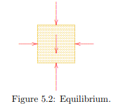
It should be noted that the vertical stress components, both the total stress and the effective stress, can be found using the condition of vertical equilibrium only, together with the assumption that the shear stresses are zero on vertical planes. The horizontal normal stresses remain undetermined at this stage. Even by also considering horizontal equilbrium these horizontal stresses can not be determined. A consideration of horizontal equilibrium, see Figure 5.2, does give some additional information, namely that the horizontal normal stresses on the two vertical planes at the left and at the right must be equal, but their magnitude remains unknown. The determination of horizontal (or lateral) stresses is one of the essenetial difficulties of soil mechanics. Because the horizontal stresses can not be determined from equilibrium conditions they often remain unknown. It will be shown later that even when also considering the deformations, the determination of the horizontal stresses remains very difficult, as this requires detailed knowledge of the geological history, which is usually not available. Perhaps the best way to determine the horizontal stresses is by direct or indirect measurement in the field.
The simple example of Figure 5.1 may be used as the strating point for more complicated cases. As a second example the situation of a somewhat lower phreatic surface is considered, say when it is lowered by 2 m. This may be caused by the action of a pumping station
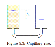
in the area, such that the water level in the canals and the ditches in a polder is to be kept at a level of 2 m below the soil surface. In this case there are two possibilities, depending upon the size of the particles in the soil. If the soil consists of very coarse material, the groundwater level in the soil will coincide with the phreatic surface (the level where p = 0), which will be equal to the water level in the open water, the ditches. However, when the soil is very fine (for instance clay), it is possible that the top of the groundwater in the soil (the groundwater level) is considerably higher than the phreatic level, because of the effect of capillarity. In the fine pores of the soil the water may rise to a level above the phreatic level due to the suction caused by the surface tension at the interface of particles, water and air. This surface tension may lead to pressures in the water below atmospheric pressure, i.e. negative water pressures. The zone above the phreatic level is denoted as the capillary zone. The maximum height of the groundwater above the phreatic level is denoted as hc, the capillary rise.
If the capillary rise hc in the example is larger than 2 meter, the soil in the polder will remain saturated when the water table is lowered by 2 meter. The total stresses will not change, because the weight of the soil remains the same, but the pore pressures throughout the soil are reduced by γw × 2 m = 20 kN/m2 . This means that the effective stresses are increased everywhere by the same amount, see Figure 5.4
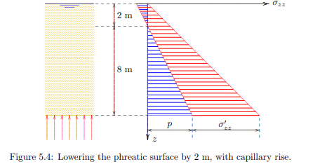
Lowering the phreatic level appears to lead to an increase of the effective stresses. In practice this will cause deformations, which will be manifest by a subsidence of the ground level. This indeed occurs very often, wherever the groundwater table is lowered. Lowering the water table to construct a dry building pit, or lowering the groundwater table in a newly reclaimed polder, leads to higher effective stresses, and therefore settlements. This may be accompanied by severe damage to buildings and houses, especially if the settlements are not uniform. If the subsidence is uniform there is less risk for damage to structures founded on the soil in that area.
Lowering the phreatic level also has some positive consequences. For instance, the increase of the effective stresses at the soil surface makes the soil much stiffer and stronger, so that heavier vehicles (tractors or other agricultural machines) can be supported. In case of a very high phreatic surface, coinciding with the soil surface, as illustrated in Figure 5.1, the effective stresses at the surface are zero, which means that there is no force between the soil particles. Man, animal and machine then cannot find support on the soil, and they may sink into it. The soil is called soggy or swampy. It seems natural that in such cases people will be motivated to lower the water table. This will result in some subsidence, and thus part of the effect of the lower groundwater table is lost. This can be restored by a further lowering of the water table, which in turn will lead to further subsidence. In some places on earth the process has had almost catastrophic consequences (Venice, Bangkok). The subsidence of Venice, for instance, was found to be caused for a large part by the production of ever increasing amounts of drinking water from the soil in the immediate vicinity of the city. Further subsidence has been reduced by finding a water supply farther form the city
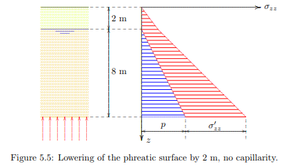
When the soil consists of very coarse material, there will practically be no capillarity. In that case lowering the phreatic level by 2 meter will cause the top 2 meter of the soil to become dry, see Figure 5.5. The upper 2 meter of soil then will become lighter. A reasonable value for the dry volumetric weight is γd = 16 kN/m3 . At a depth of 2 m the vertical effective stress now is σ 0 zz = 32 kPa, and at a depth of 10 m the effective stress is σ 0 zz = 112 kPa. It appears that in this case the effective stresses increase by 12 kPa, compared to the case of a water table coinciding with the ground surface. The distribution of total stresses, effective stresses and pore pressures is shown in Figure 5.5. Again there will be a tendency for settlement of the soil. In later chapters a procedure for the calculation of these settlements will be presented. For this purpose first the relation between effective stress and deformation must be considered.
Subsidence of the soil can also be caused by the extraction of gas or oil from soil layers. The reservoirs containing oil and gas are often located at substantial depth (in Groningen at 2000 m depth). These reservoirs usually consist of porous rock, that have been consolidated through the ages by the weight of the soil layers above it, but some porosity (say 10 % or 20 %) remains, filled with gas or oil. When the gas or oil is extracted from the reservoir, by reducing the pressure in the fluid, the effective stresses increase, and the thickness of the reservoir will be reduced. This will cause the soil layers above the reservoir to settle, and it will eventually give rise to subsidence of the soil surface. In Groningen the subsidence above the large gas reservoir is estimated to reach about 50 cm, over a very large area. All structures subside with the soil, with not very much risk of damage, as there are no large local variations to be expected. However, because the soil surface is below sea level, great care must be taken to maintain the drainage capacity of the hydraulic infrastructure. Sluices may have to be renewed because they subside, whereas water levels must be maintained. The dikes also have to be raised to balance the subsidence due to gas production.
In some parts of the world subsidence may be far more serious, for instance in areas of coal mining activities. In mining the entire soil is being removed, and sudden collapse of a mine gallery may cause great damage to the structures above it.