For the theoretical analysis of groundwater flow several computational methods are available, analytical or numerical. Studying groundwater flow is of great importance for soil mechanics problems, because the influence of the groundwater on the behaviour of a soil structure is very large. Many dramatic accidents have been caused by higher pore water pressures than expected. For this reason the study of groundwater flow requires special attention, much more than given in the few chapters of this book. In this chapter one more example will be presented: the flow caused by wells. Direct applications include the drainage of a building pit, or the production of drinking water by a system of wells.
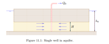
The solutions to be given here apply to a homogeneous sand layer, confined between two impermeable clay layers, see Figure 11.1. This is denoted as a confined aquifer , assuming that the pressure in the groundwater is sufficiently large to ensure complete saturation in the sand layer.
In this case the groundwater flows in a horizontal plane. In this plane the cartesian coordinate axes are denoted as x and y. The groundwater flow is described by Darcy’s law in the horizontal plane
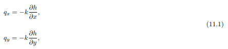
and the continuity equation for an element in the horizontal plane,

It now follows, if it is assumed that the hydraulic conductivity k is costant, that the partial differential equation governing the flow is
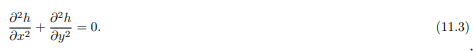
This is again Laplace’s equation, but this time in a horizontal plane.
The problem to be considered concerns the flow in a circular region, having a radius R, to a well in the center of the circle. This is an important basic problem of groundwater mechanics. The boundary conditions are that at the outer boundary (for r = R) the groundwater head is fixed: h = h0, and that at the inner boundary, the center of the circle, a discharge Q0 is being extracted from the soil. It is postulated that the solution of this problem is

where Q0 is the discharge of the well, k the hydraulic conductivity of the soil, H the thickness of the layer, h0 the value of the given head at the outer boundary (r = R), and r is a polar coordinate,

That the expression (11.4) indeed satisfies the differential equation (11.3) can be verified by substitution of this solution into the differential equation. The solution also satisfies the boundary condition at the outer boundary, because for r = R the value of the logarithm is 0 (ln(1) = 0). The boundary condition at the inner boundary can be verified by first differentiating the solution (11.4) with respect to r. This gives

This means that the specific discharge in r-direction is, using Darcy’s law,

The total amount of water flowing through a cylinder of radius r and height H is obtained by multiplication of the specific discharge qr by the area 2πrH of such a cylinder,

This quantity appears to be constant, independent of r, which is in agreement with the continuity principle. It appears that through every cylinder, whatever the radius, an amount of water −Q0 is flowing in the positive r-direction. That means that an amount of water +Q0 is flowing towards the centre of the circle. That is precisely the required boundary condition, and it can be conclude that the solution satisfies all conditions, and therefore must be correct.
The flow rate very close to the centre is very large, because there the discharge Q0 must flow through a very small surface area. At the outer boundary the available is very large, so that there the flow rate will be very small, and therefore the gradient will also be small. This makes it plausible that the precise form of the outer boundary is not so important. The solution (11.4) can also be used, at least as a first approximation, for a well in a region that is not precisely circular, for instance a square. Such a square can then be approximated by a circle, taking care that the total circumference is equal to the circumference of the square.
It may be noted that everywhere in the aquifer r < R. Then the logarithm in eq. (11.4) is negative, and therefore h < h0, as could be expected. By pumping the groundwater head will be lowered.

Comments are closed