The second example is concerned with a pipeline in the bottom of the sea (or a circular tunnel under a river), see Figure 9.3. The pipeline is supposed to consist of steel, with a concrete lining, having a diameter 2R and a total weight (above water) G, in kN/m. This weight consists of
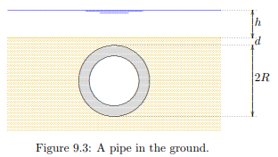
the weight of the steel and the concrete lining, per unit length of the pipe. For the risk of floatation the most dangerous situation will be when the pipe is empty.
For the analysis of the stability of the pipeline it is convenient to express its weight as an average volumetric weight γp, defined as the total weight of the pipeline divided by its volume. In the most critical case of an empty pipeline this is

The buoyant force F on the pipeline is, in accordance with Archimedes ‘principle,

where γw is the volumetric weight of water. If the upward force F is smaller than the weight G there will be no risk of floatation. The pipeline then sinks in open water. This will be the case if γp > γw. For a pipeline on the bottom of the sea this is a very practical criterion. If one would have to rely on the weight of the soil above the pipeline for its stability, floatation might occur if the soil above the pipeline is taken away by erosion. The pipeline then might float to the sea surface.
In case of a tunnel under a river there seems to be more certainty that the soil above the tunnel remains in place. Then the weight of the soil above the tunnel may prevent floatation even if the tunnel is lighter than water (γp < γw). The weight W of the soil above the tunnel is

where γs is the volumetric weight of the soil, and d is the cover thickness, the thickness of the soil at the top of the tunnel. It is now essential to realize, in accordance with Archimedes’ principle that for the stability of the tunnel the soil above only contributes insofar as it is heavier than water. The water above the tunnel does not contribute. A block of wood will float in water, even if the water is very deep. This means that the effective downward force of the soil above the tunnel is

the difference of the weight of the soil and the weight of the water in the same volume. The amount of soil that is minimally needed now follows from the condition
fomr which the ground cover d can be calculated. There still is some additional safety, because when the tunnel moves upward the soil above it must shear along the soil next to it, and the friction force along that plane has been disregarded. It is recommended to keep that as a hidden reserve, because floatation is such a serious calamity.
The analysis can, of course, also be performed in the more standard way of soil mechanics stress analysis: determine the effective stress as the difference of the total stress and the pore pressure. The procedure is as follows
The average total stress below the tunnel is (averaged over its width 2R)

where h is the depth of the water in the river.
The average pore pressure below the tunnel is determined by the volume of the space occupied by the tunnel and everything above it, up to the water surface,

The average effective stress below the tunnel now is

The condition that this must be positive, because the particles cannot transmit any tensile force, leads again to the criterion (9.11).