As a first example a concrete floor of an excavation is considered. Such structures are often used as foundations of basements, or as the pavement of the access road of a tunnel. One of the functions of the concrete plate is to give additional weight to the soil, so that it will not float. Care must be taken that the water table can only be lowered when the concrete plate is already present. Therefore a convenient procedure is to build the concrete plate under water, before the lowering of the water table, see Figure 9.2. After excavation of the pit, under water, perhaps using dredging equipment, the concrete floor must be constructed, taking great care of the continuity of the floor and the vertical walls of the excavation. When the concrete structure has been finished, the water level can be lowered. In this stage the weight of the concrete is needed to prevent floatation.
There are two possible methods to perform the stability analysis. The best method is to determine the effective stresses just below the concrete floor. If these are always positive, in every stage of the building process, a compressive stress is being transferred in all stages, and the structure is safe. Whenever tensile stresses are obtained, even in a situation that is only temporary, the design must be modified. The structure will not always be in equilibrium, and will float or break. It is assumed that in the case shown in Figure 9.2 the groundwater level is at a depth
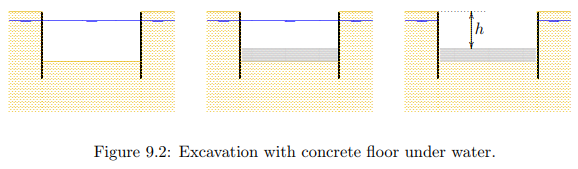
d = 1 m below the soil surface, and that the depth of the top of the concrete floor should be located at a depth h = 5 m below the soil surface. Furthermore the thickness of the concrete layer (which is to be determined) is denoted as D. The total stress just below the concrete floor now is

where γc is the vlumetric weight of the concrete, say γb = 25 kN/m3. The pore pressure just below the concrete floor is

so that the effective stress is

The requirement that this must be positive gives

The effective stress will be positive if the thickness of the concrete floor is larger than the critical value. In the example, with h − d = 4 m and the concrete being a factor 2.5 heavier than water, it follows that the thickness of the floor must be at least 2.67 m. It may be noted that the required thickness of the concrete floor should be somewhat larger, namely 3.33 m if the groundwater level would coincide with the soil surface. One must be very certain that this condition cannot occur if the concrete plate is taken thinner as 3.33 m. It may also be noted that in time of danger, perhaps when the groundwater pressures rises because of some emergency, the foundation can be saved by submerging with water.
The analysis can be done somewhat faster by directly requiring that the weight of the concrete must be sufficient to balance the upward force acting upon it from below. This leads to the same result. The analysis using the somewhat elaborate process of calculating the effective stresses may take some more time, but it can more easily be generalized, for instance in case of a groundwater flow, when the groundwater pressures are not hydrostatic.
The concrete floor in a structure as shown in Figure 9.2 may have to be rather thick, which requires a deep excavation and large amounts of concrete. In engineering practice more advanced solutions have been developed, such as a thin concrete floor, combined with tension piles.
It should be noted that this requires a careful (and safe) determination of the tensile capacity of the piles. A heavy concrete floor may be expensive, its weight is always acting.