Kinematical analysis of a structure can also be done using the static equations. The following criteria for instantaneously changeable systems may be used:
(a) Load has finite quantity but the internal forces have infinite values
(b) Load is absent and the internal forces are uncertain (type of 0/0)
Let us discuss these criteria for structure shown in Fig. 1.6a.
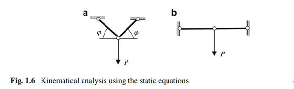
Internal forces in members of the structure are N D P = .2 sin ‘/. If ‘ D 0 (Fig. 1.6b), then N D 1. Thus, external load P of finite quantity leads to the internal forces of infinite values. It happens because the system is instantaneously changeable. Indeed, two rigid discs are connected using three hinges located on the one line.
Figure 1.7 presents the design diagram of the truss. This structure is generated from simplest rigid triangle; each next joint is attached to previous rigid disc by two end-hinged links. The structure contains three support constraints, which are necessary minimum for plane structure. However, location of these supports may be wrong. Thorough kinematical analysis of this structure may be performed by static equations. Reaction R of support may be calculated using equilibrium condition
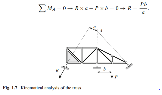
1. If a D 0, then for any external load P the reaction of the left support is infinitely large .R D P b=0/
2. If a D 0 and P D 0, then reaction R is uncertain .R D 0=0/. Thus, if all lines of support constraints are concurrent at one point .a D 0/, then this case leads to instantaneously changeable system.
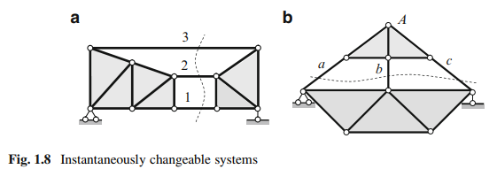
Instantaneously changeable systems may occur if two rigid discs of a structure join inappropriately. Two such connections of rigid discs are shown in Fig. 1.8. If a system may be separated into two rigid discs (shown by solid color) by a section cutting three elements, which are parallel (Fig. 1.8a, elements 1, 2, 3), or concurrent in one point (Fig. 1.8b, point A, elements a, b, c), then the system is instantaneously changeable one.
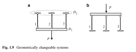
However, in practice, connection of two rigid discs by two (or more) parallel members may be used in special condition of loading. Figure 1.9 presents the rigid beam (disc D1), which is supported by vertical hinged-end rods 1–3 (disc D2 is a support part). The system may be used if the axial forces in members 1–3 are tensile (Fig. 1.9a). However, the system cannot be used if the axial forces in members 1–3 are compressive (Fig. 1.9b).
Evolution of the structure caused by changing the type of supports is shown in Fig. 1.10. Constraint A (Fig. 1.10a) prevents two displacements, in vertical and horizontal directions. If one element of the constraint A, which prevents horizontal displacement, will be removed, then the structure becomes geometrically changeable (Fig. 1.10b), so the removed constraint is the required one. In case of any horizontal displacement of the structure, all support constraints A, B, and C remain parallel to each other.
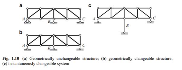
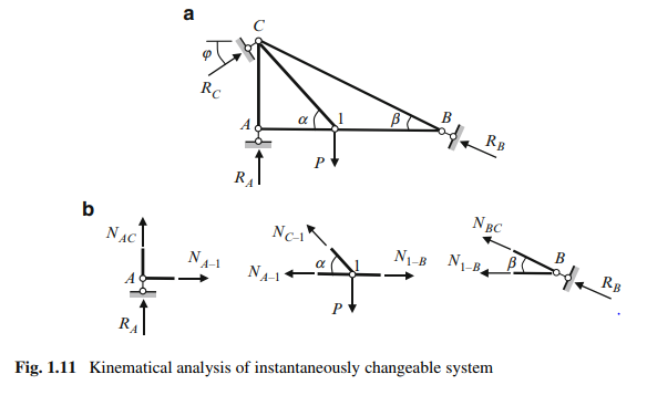
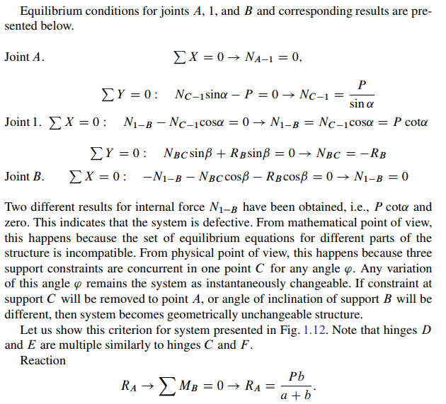
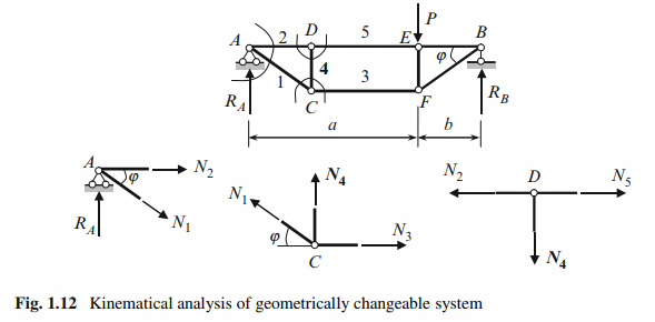
The next evolution is presented in Fig. 1.10c. If any support, for example supporting element B will be longer than other supports, then structure becomes instantaneously changeable system. Indeed, in case of any horizontal displacement of the structure, the support constraints will not be parallel any more. It is worth to mention one more static criterion for instantaneously changeable and geometrically changeable structures: internal forces in some element obtained by two different ways are different, or in another words, analysis of a structure leads to contradictory results. This is shown in the example below. Design diagram of the truss is presented in Fig. 1.11a: the constraint support B is directed along the element BC. The system has the necessary minimum number of elements and constraints to be geometrically unchangeable structure. Let us provide more detailed analysis of this structure. Free body diagrams and equilibrium conditions for joints A, 1, and B are shown in Fig. 1.11b.
We received for internal force N4 two contradictory (or inconsistent) results. Why this happens? To answer on this question let us consider the very important concept “degrees of freedom.”