So far, we have been considering cases when external loads were applied directly to the beams. In practice, however, loads are often applied to secondary beams (or stringers) and then are transmitted through them to the main beam (or girder) as shown in Fig. 2.15. Stringers are simply supported beams. Each stringer’s span is called a panel d and each point where the stringer transmits its load onto the main beam is called a panel point or a joint. The load is transmitted from the secondary beams onto the main beam only at panel points.
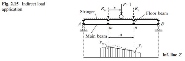
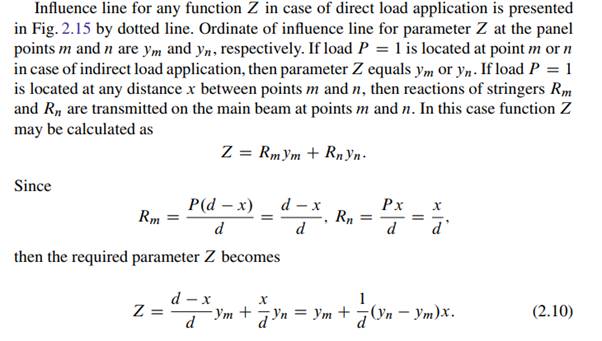
Thus, the influence line for any function Z between two closest panel points m and n is presented by a straight line. This is the fundamental property of influence lines in case of indirect load application.
Influence lines for any function Z should be constructed in the following sequence:
1. Construct the influence line for a given function Z as if the moving load would be applied directly to the main beam.
2. Transfer the panel points on the influence line and obtained nearest points connect by straight line, which is called as the connecting line.
This procedure will be widely used for construction of influence lines for arches and trusses.
Procedure for construction of influence lines of bending moment and shear at section k for simply supported beam in case of indirect load application is shown in Fig. 2.16. First of all we need to construct the influence line for these functions if load P would be applied directly to the main beam AB. Influence line for bending moment presents triangle with vertex ab=l at the section k; influence line for shear is bounded by two parallel lines with the jump at the section k. Then we need to indicate the panel points m and n, which are nearest to the given section k, and draw vertical lines passing through these points. These lines intersect the influence lines at the points m0 and n0 . At last, these points should be connected by a straight line.
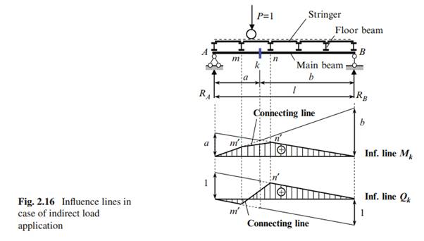
Pay attention, that if a floor beam m will be removed, then the influence line for Qk becomes the positive one-sign function instead of a two-sign function, as presented in Fig. 2.16. If the floor beam n and all following ones (except floor beam at the support B) will be removed, then the influence line for Qk becomes the one sign function too, but a negative one.