Gerber–Semikolenov beams may be schematically presented in the form, which shows the interaction of separate parts and transmission of forces from one part of the beam to another. Gerber–Semikolenov beams consist of two types of beams, namely a main (or primary) and suspended (or secondary) beam.
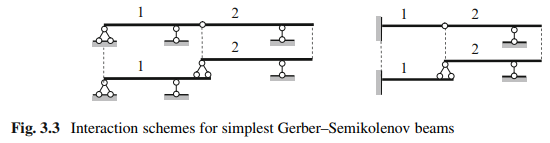
A main beam is designed to carry a load, which is applied to this beam as well as to maintain a suspended beam. Therefore, the main beam carries a load, which is applied to this beam, as well as a load, which is transmitted on the main beam as a reaction of the suspended beam. Interaction schemes for simplest Gerber– Semikolenov beams are presented in Fig. 3.3.
In these cases, beams 1 are primary and beams 2 are secondary ones. Obviously, that failure of the beam 1 causes the collapse of the entire structure while failure of the beam 2 does not cause failure of the beam 1. There is only one way of presenting multispan beams using an interaction diagram.
Interaction schemes allow to clearly indicate the load pass from one part of a structure to another. Also they are helpful for construction of internal force diagrams as well as for more advanced analysis.
Five-span beam and its interaction diagram is presented in Fig. 3.4. Since the structure in a whole is restricted against the horizontal displacement owing to support A, then each part of the structure has no displacement in horizontal direction as well. That is why the rolled supports C and E on the interaction diagram are replaced by pinned supports. Restrictions for suspended beams also prevent horizontal displacements. This replacement is conventional.
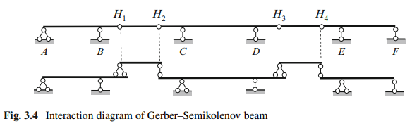
Beams ABH1 and H1H2 present the main and suspended beams, respectively. It means that collapse of the main beam ABH1 leads to the collapse of suspended beam, while collapse of suspended beam does not affect on the main beam. Collapse of the beam H4EF leads to the collapse of the beam H3H4 only, and does not affect on other parts of the structure. The entire structure contains five discs, four simple hinges, and seven constraints of supports. Degree of freedom of the structure is

so entire system is statically determinate and geometrically unchangeable structure. On the other hand, in general case of loads there are seven reactions of supports arise in the structure. For their calculation we can use three equilibrium equations and four additional conditions, i.e., bending moment at each hinge is equal to zero. Therefore, the structure is statically determinate one. Another four-span beam and its interaction diagram is presented in Fig. 3.5. The entire structure contains four discs, three simple hinges, and six constraints of supports. Degree of freedom of the structure is

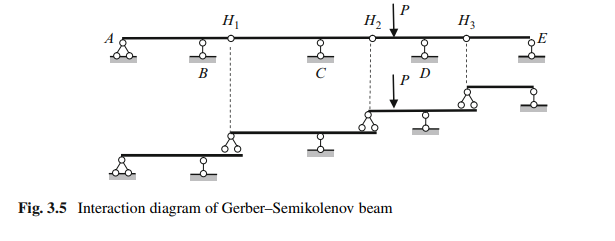
so entire system is statically determinate and geometrically unchangeable structure. On the other hand, in general case of loads there are six reactions of supports arise in the structure; they are five vertical reactions at supports and one horizontal reaction at support A. For their calculation we can use three equilibrium equations and three additional conditions, i.e., the bending moment at each hinge is equal to zero. Therefore, the structure is statically determinate one.
The beam H2H3 is both main for H3E beam and suspended for H1CH2 one. Therefore, the load P, which is applied to the beam H2H3 is transmitted only to beams located below and does not transmitted to the beams located above this one.
It is not difficult to form the rules of distribution of hinges which transforms the continuous beam with one (or two) clamped ends into Gerber–Semikolenov beam.