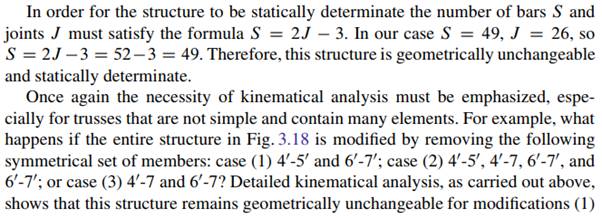
The Baltimore truss is widely used in bridge-building for cases involving particularly long spans and large loads. The classical Baltimore truss is a Pratt truss strengthened by two additional members in each panel (members 2-4 and 3-4 in Fig. 3.16a). The modified Baltimore truss is a Pratt truss strengthened by three additional members in each panel (members 3-4, 2-4, and 4-6 in Fig. 3.16b). In both cases, truss 1-2-3-4 should be treated as a secondary truss. This triangular truss is supported by joints 1 and 3 of the main truss. In both cases, the vertical load, which is applied to the loaded chord and acts at joint 2, leads to vertical reactions of the secondary truss. These reactions are transmitted as active loads on the joints of the same chord of the main truss.
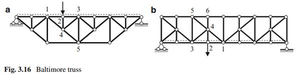
In order to reduce the length of the compressed member of the upper chord, member 2-4 is used in case (a) and additional member 4-6 in case (b).
Analysis of such trusses can be performed by considering the entire structure as a combination of a Pratt truss (the main truss) and a set of additional triangular trusses: one of them is additional truss 1-2-3-4.
There are three groups of elements: the ones that belong to the main truss only (bars 3-5 and 4-5), the ones that belong to the secondary truss only (bars 2-4, 3-4, and 4-6); and others that belong to both the main and the secondary trusses (bars 1-4, 1-2, and 2-3).
The same principle will be used for the construction of influence lines.
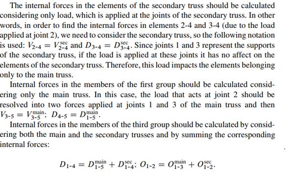
Another type of this class of trusses is the subdivided Warren truss. This truss is generated from a simple Warren truss using the same generation principle used for a Baltimore truss.
Let us consider a detailed analysis of a subdivided Warren truss presented in Fig. 3.17. The moving load is applied to the lower chord. As usual, we start from a kinematical analysis. This truss is geometrically unchangeable because the rigid discs are connected by means of hinges and bars.
and (2). However, for modification (3) this structure becomes geometrically changeable and cannot be used as an engineered structure. Unfortunately, some modern software will work out a numerical analysis for any structure, even if the structure is changeable. Therefore, in order to avoid structural collapse, each engineer must complete a kinematical analysis as the very first step.
The entire structure in Fig. 3.18 can be represented as a combination of main and secondary trusses. A feature of this subdivided Warren truss is the following: if the load is located on joints 10 , 30 , 50 , etc. of the secondary trusses on the lower chord, then the reactions of the secondary trusses are transmitted as active loads to the joints of the lower chord of the main truss
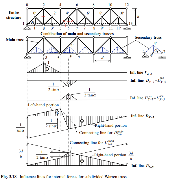
Now we will consider the construction of influence lines for reactions and internal forces of elements belonging to three different groups, i.e., to the main truss only, to a secondary truss only, and to both trusses simultaneously. These elements are indicated in Fig. 3.18.
Influence lines for reactions are constructed in the same manner as in the case of a simple truss. These influence lines are not shown. The construction of influence lines for internal forces is presented in tabulated form below.


Comments are closed