
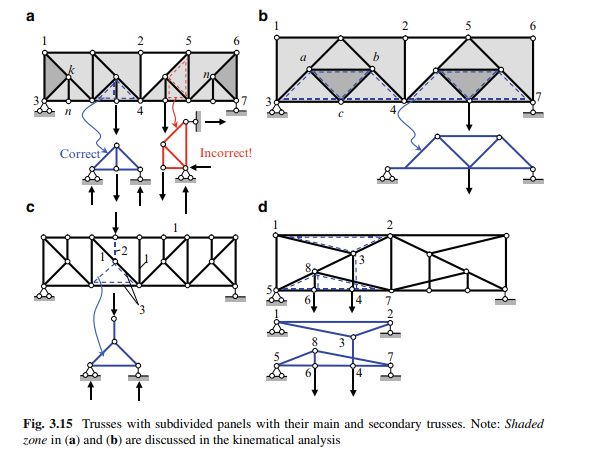
Trusses with subdivided panels present are simple trusses with additional members. Figure 3.15a shows the Pratt truss with two additional members within each panel; for first panel they are 3-k and k-n. Figure 3.15b shows the Parker truss with three additional members within each panel; they are a-b, a-c and b-c. In both examples additional elements divide a panel (vertical member k-n in first case and inclined members a-c and b-c in the second case). In the analysis of such trusses, an immediate application of the joints and through section methods might lead to some difficulties.
Main and Auxiliary Trusses and Load Path
Analysis of trusses with subdivided panels can be performed in an orderly fashion using the concepts of the main and secondary (auxiliary) trusses. The main truss is a simple truss, which is enhanced by additional members. The secondary truss is a conventional truss, which contains additional real members (3-k and k-n for truss in Fig. 3.15a) and some imaginary members. These imaginary members coincide with members of the main truss. The secondary trusses are shown by dotted lines. The concepts of the main and secondary trusses allow us to consider trusses with subdivided panels as compound trusses. Combinations of two trusses – a main and sets of secondary trusses are shown in Fig. 3.15. In all cases, the secondary trusses are supported by the joints of the main truss.
The main purpose of a secondary truss is to transmit a load, which is applied between the joints of a main truss, to the joints of a main truss.
How can we distinguish between the main and the secondary trusses? The rule is that elements of the secondary truss are connected with the main truss in such a way that a vertical load, which acts on the joint of the secondary truss, is transmitted only as a vertical load to the joints of the main truss. The secondary trusses in Fig. 3.15 are shown by dotted lines. Figure 3.15a also shows an incorrect presentation of a secondary truss, since in this case the vertical, as well as the horizontal reactions are transmitted to the joints of the main truss.
Auxiliary trusses add joints to the loaded chord and serve different goals:
1. Secondary elements (i.e., the elements of the auxiliary truss) transmit loads applied to the lower (or upper) chord to the joints of the same chord of the main truss (Fig. 3.15a, b).
2. Secondary elements transmit loads applied to the upper (or lower) chord to the joints of the other chord of the main truss (Fig. 3.15c).
3. Vertical elements of an auxiliary truss can divide a compressed member of the upper chord, leading to increased load-carrying capacity of this element (Fig. 3.15c).
It is possible to have a combination of two types of auxiliary trusses so that a load is transmitted to both chords of the main truss as shown in Fig. 3.15d. In this case hinge 6 belongs to bottom auxiliary truss 5-8-7-6, while hinge 4 belongs to top auxiliary truss 1-2-3-4. Members 3-4 and 7-8 have no common points. If load P is located at point 4, then the load is transmitted to the upper chord (to joints 1 and 2) of the main truss. If load P is located at point 6, then the load is transmitted to the lower chord (to joints 5 and 7) of the main truss. If load P is located between points 4 and 6, then part of the load is transmitted to joint 4 and part to joint 6, and from there it is transmitted from joint 4 to an upper chord and from joint 6 to lower chord.
Kinematical Analysis
For kinematical analysis of the truss in Fig. 3.15a, we show the initial rigid disc 1-3-k. Each subsequent hinge is connected using two bars with hinges at the ends, thus part 1-2-4-3 of the truss presents a rigid disc. The next joint cannot be obtained in this way, so instead consider the truss from the right where the base rigid triangle is 6-7-n. Similarly, each subsequent hinge is connected using two bars with hinges at the ends, so part 5-6-7-4 presents a second rigid disc. Both discs are connected by hinge 4 and member 2-5 according to Fig. 3.9; this compound truss is geometrically unchangeable. The trusses in Fig. 3.15b,c can be analyzed in a similar way.
For all the design diagrams presented in Fig. 3.15, the relationship S = 2J – S0 is satisfied. For example, for structures (a,c) S = 33 and J = 18; for structures (b,d) S = 25, and J = 14. All these structures are statically determinate and geometrically unchangeable compound trusses.
The elements of trusses with subdivided panels can be arranged into three groups as follows:
1. The elements belonging to the main truss only. The internal forces in these elements are not influenced by the presence of secondary trusses. Such elements are labelled #1 in Fig. 3.15c.
2. The elements belonging to the secondary system only. The internal forces in these elements arise if a load is applied to the joints of the secondary system. Such elements are labelled #2.
3. The elements belonging simultaneously to both the main and the secondary trusses. The internal forces in such members are obtained by summing the internal forces, which arise in the given element of the main and also of the secondary trusses, calculated separately. Such elements are labelled #3.

Comments are closed