
For construction of influence lines of reactions and internal forces for statically determinate multispan beams the following steps are recommended:
Step 1. The entire multispan hinged beam should be presented in the interaction diagram form. This helps to classify each element of the structure as primary or secondary beams, and visualize the load path from the secondary beam on the primary one.
Step 2. Consider structural element of a multispan beam, which contains a support or section for which the required influence line should be constructed. This element is the primary or secondary simply supported beam with/without overhangs or cantilevered beam. Then we need to construct an influence line for the required function for this beam only.
Step 3. Take into account the influence of moving load which is located on the adjacent suspended beam and distribute the influence line which is constructed in step 2 along this secondary beam. For this it is necessary to connect an ordinate of influence line at the end point (hinge) with a zero ordinate at the second support of the suspended beam. This procedure is called as distribution of influence lines within the suspended beam.
Step 4. The beam distribution procedure should be applied for the following suspended beam. To illustrate this procedure for statically determinate multispan beams we will consider a structure as in Fig 3.6. It is necessary to construct the influence lines for reactions, bending moment, and shear for indicated sections. We are starting from kinematical analysis of a structure: this beam is statically determinate and geometrically unchangeable structure.
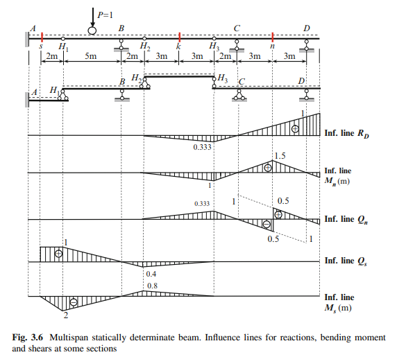
Influence Lines for Shear Qk, and Bending Moment Mk at Section k
Suspended beam H2H3 is subjected to loads, which act on this beam only, while a load from other parts of the beam (AH2 and H3D) cannot be transmitted on the beam H2H3. Therefore influence lines for internal forces at section k are same as for simply supported beam without overhangs.
Influence Lines for Shear Qn, and Bending Moment Mn at Section n
Influence lines for section n should be constructed as for simply supported beam with overhang H3C. At point H3 this beam supports the beam H2H3, which is suspended one. Therefore, ordinates of influence lines at point H3 should be connected with zeros ordinates at point H2.
Influence Lines for Shear Qs, and Bending Moment Ms at Section s
When the load travels along portion AH1, then construction of the influence lines for section s is exactly the same as for a cantilevered beam. If load P D 1 is located on the suspended beam H1H2, then fraction of this force is transmitted to the primary beam AH1. If load P D 1 is located at point H1 of suspended beam H1BH2, then this force is completely transmitted to the primary beam AH1. Therefore, influence line has no discontinuity at point H1
If load P D 1 is located at point B on the suspended beam H1BH2, then this force is completely transmitted to the support B and no part of this force is taken by the support H1 and thus, no force is transmitted to the main beam AH1. Therefore, influence lines for shear and moment at section s has zero ordinates at point B. If unit load is located within the H1BH2, then the pressure from the secondary beam on the primary beam at point H1 varies proportionally to the distance of the unit load from point B.
Similar discussions should be used, when unit load travels along the suspended beam H2H3. If load travels along the beam H3CD, then no part of this load is transmitted to the beam AH1. Therefore, ordinates on influence lines for Qs and Ms along the part H3CD are zeros.
If load is located within the part s-B, then bending moment at section s is negative. It means, that the extended fibers at section s are located above the neutral line. If any load will be distributed within BH3, then extended fibers at section s will be located below the neutral line.


Comments are closed