The arches are widely used in modern engineering. Arches permit to cover a larger span. The greater is the span than an arch becomes more economical than a truss. From aesthetic point of view the arches are more attractive than trusses. Materials of the modern arches are concrete, steel, and wood. The body of the arch may be solid or consist of separate members. The arches are classified as three-hinged, two-hinged, and arch with fixed supports. A three-hinged arch is geometrically unchangeable statically determinate structure which consists of two curvilinear members, connected together by means of a hinge, with two-hinged supports resting on the abutment. This chapter is devoted to analyse only three-hinged arches. Two-hinged arch and arch with fixed supports will be considered in Part 2.
Preliminary Remarks
Design Diagram of Three-Hinged Arch
The arch with overarched members is shown in Fig. 4.1a. The arch contains three hinges. Two of them are located at the supports and third is placed at the crown. These hinges are distinguishing features of the three-hinged arch. Design diagram also contains information about the shape of the neutral line of the arch. Usually this shape is given by the expression, y = f .x/.
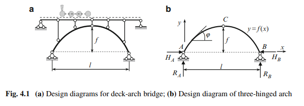
Each post which connects the beams of overarched structure with arch itself has the hinges at the ends. It means that in the poles only axial force arises. Idealized design diagram of the three-hinged arch without overarched members is shown in Fig. 4.1b.
Degrees of freedom of three-hinged arch according to Chebushev formula (1.1) is W D 0, so this structure is geometrically unchangeable. Indeed, two rigid discs AC and BC are connected with the ground by two hinges A and B and line AB does not pass through the intermediate hinge C.
This structure has four unknown reactions, i.e., two vertical reactions RA, RB and two horizontal reactions HA, HB . For their determination, three equilibrium equations can be formulated considering the structure in whole. Since bending moment at the hinge C is zero, this provides additional equation for equilibrium of the part of the system. It means that the sum of the moments of all external forces, which are located on the right (or on the left) part of the structure with respect to hinge C is zero
These four equations of equilibrium determine all four reactions at the supports. Therefore, three-hinged arch is a geometrically unchangeable and statically determinate structure.
Peculiarities of the Arches
The fundamental feature of arched structure is that horizontal reactions appear even if the structure is subjected to vertical load only. These horizontal reactions HA D HB D H are called a thrust; such types of structures are often called as thrusted structures.
It will be shown later that at any cross section of the arch the bending moments, shear, and axial forces arise. However, the bending moments and shear forces are considerably smaller than corresponding internal forces in a simply supported beam covering the same span and subjected to the same load. This is the fundamental property of the arch thanks to thrust. Thrusts in both supports are oriented toward each other and reduce the bending moments that would arise in beams of the same span and load. Therefore, the height of the cross section of the arch can be much less than the height of a beam to resist the same loading. So the three-hinged arch is more economical than simply supported beam, especially for large-span structures.
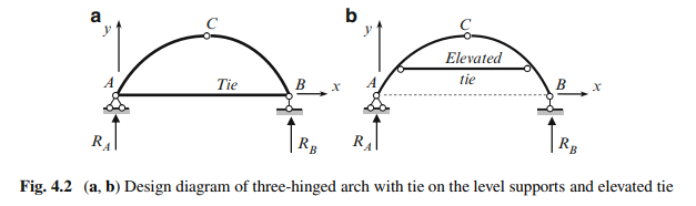
Both parts of the arch may be connected by a tie. In this case in order for the structure to remain statically determinate, one of the supports of the arch should be rolled (Fig. 4.2a, b).
Prestressed tie allows controlling the internal forces in arch itself. Tie is an element connected by its ends to the arch by mean of hinges, therefore the tie is subjected only to an axial internal force. So even if horizontal reactions of supports equal zero, an extended force (thrust) arises in the tie
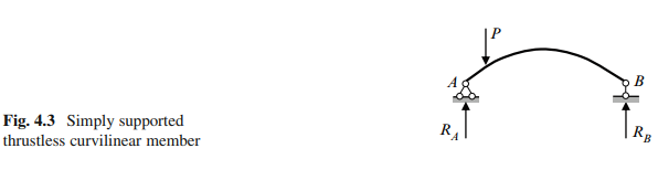
Thus, the arch is characterized by two fundamental markers such as a curvilinear axis and appearance of the thrust. Therefore the structure in Fig. 4.3 presents the curvilinear trustless simply supported element, i.e., this is just members with curvilinear axis, but no arch. It is obvious that, unlike the beam, in this structure the axial compressed forces arise; however, the distribution of bending moments for this structure and for beam of the same span and load will not differ, while the shear forces are less in this structure than that in beam. Thus, the fundamental feature of the arch (decreasing of the bending moments due to the appearance of the thrust) for structure in Fig. 4.3 is not observed.
Geometric Parameters of Circular and Parabolic Arches
Distribution of internal forces in arches depends on a shape of the central line of an arch. Equation of the central line and some necessary formulae for circular and parabolic arches are presented below. For both cases, origin of coordinate axis is located at point A (Figs. 4.1b and 4.2).
Circular Arch
Ordinate y of any point of the central line of the arch is defined by formula
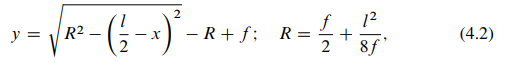
where x is the abscissa of the same point of the central line of the arch; R the radius of curvature of the arch; f and l are the rise and span of the arch.
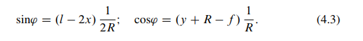
The angle ‘ between the tangent to the center line of the arch at point .x; y/ and horizontal axis is shown in Fig. 4.1b. Trigonometric functions for this angle are as follows:
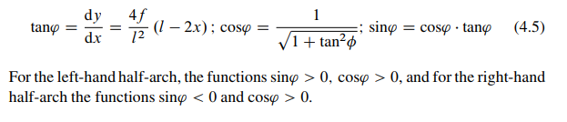
Parabolic Arch
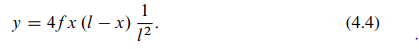
Ordinate y of any point of the central line of the arch
Trigonometric functions of the angle between the tangent to the center line of the arch at point .x; y/ and a horizontal axis are as follows
Comments are closed