Pressure valves in the Chunnel involve an important design concept. The designers of the Chunnel have optimized the air dynamics inside the tunnel so that passengers inside a train feel almost no effect due to pressure changes. How did they achieve this feat?
What is the Channel Tunnel?

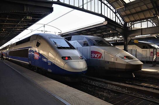
The Channel Tunnel, which is popularly known as the Chunnel, is an undersea rail tunnel that runs between the United Kingdom and France mostly under the English Channel. This is the second largest undersea channel in the world and has the largest under sea portion of any tunnel. The Chunnel is used for high speed passenger trains, international rail freight trains, and vehicle transport by Eurotunnel Shuttle.
In the Chunnel, a from “Paris to London journey” takes only two hours and fifteen minutes, thanks to the extreme efforts of the designers and workers. Due to its complexity in designing and greater risks in construction, the Chunnel is considered one of the engineering marvels in the modern world. Also it was named one of the Seven Wonders of the Modern World by the American Society of Civil Engineers in 1996.
During the design process engineers had to face severe challenges because of the extreme nature of the project… when they began the constructions in 1988. Several interesting design concepts were involved with the Chunnel, which opened in 1994. One such concept was thepressure relief valve system of theChannel Tunnel.
The Design of the Channel Tunnel

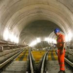
The Channel Tunnel links Folkestone, Kent in the United Kingdom with Coquelles, Pas-de-Calais in northern France by a 50.5kilometer long undersea rail tunnel. It consists of two 7.6 m internal diameter rail tunnels and a 4.8 internal diameter service tunnel. All three tunnels are 50.5 km in length and the service tunnel lies between rail tunnels that are spaced 30 m apart. There are pairs of cross passages that connect rail roads to the service tunnel. They are located along the whole route spacing at 375 m. Each of these cross passages has an internal diameter of 3.3 m. Also there are piston relief ducts of 2 m internal diameter for connecting rails tunnels at 250 m spacing. Knowing how these pressure valves in the Chunnel work is quite important when we analyze this remarkable civil engineering feat. The average depth of the Chunnel under the seabed is 45 meters. 37.9 km of the total length is under sea. The total cost for the Channel Tunnel project was $21 billion. That’s 700 times more expensive than the cost of the Golden Gate Bridge in the US.

The service tunnel is used to provide fresh air ventilation, entrance to cross-passages and equipment rooms, and for emergency evacuation. The Service Tunnel Transport System (STTS) allows quick access to all areas of the tunnel. Rail tunnels are used by passenger trains travelling at a very high speed. When a train moves in a tunnel, they dominate the air flow in the tunnel creating massive variations of air pressure. This may create problems for the passengers in the train. This is one of the main considerations in the design of the Channel Tunnel.
Air Dynamics in a Tunnel
When a train passes through a channel, usually it occupies almost all the cross section of the channel by seriously limiting the movement of air. In the open air, when a train (or any other vehicle) travels along the road, air is always being pushed away by the vehicle. In this case, air can move anywhere except into the ground. But in a tunnel, air can’t move anywhere except along the tunnel and air has to be pushed away along the tunnel. Therefore when the train moves, the air pressure behind the train is very low as the air is pushed away by the train. To compensate for that low air pressure, suction is created by pulling air into the tunnel. Actually this process is called piston effect as this is similar to the piston inside an engine. Due to low pressure at the back of the train there is a movement of air from front to back over the length of the train. This pressure gradient further increases the aerodynamic drag of the train.
Let’s find out how the pressure valves and ducts increase passenger comfort and train efficiency.
Pressure valves in the Chunnel work to reduce the air pressure and drag on the trains that drive inside the tunnel. The Channel Tunnel designers have optimized the spacing of these pressure relief valves (piston relief ducts) by using air dynamic calculations and computer simulations. How pressure valves in the Chunnel work? How actually these pressure control valves have been able reduce air pressure? These are questions raised by many interested parties. The Chunnel Channel is the second longest undersea channel in the world and has the longest undersea portion. Its pressure valve system is another incredible design. It would be quite interesting to know how this pressure relief valves work.

The air resistance (drag) is proportional to the squared value of the speed of the train. At very high speeds, drag forces become very high so that the train needs extra power (engine power) to move forward. In a shorter tunnel, the slowing of the train can be neglected due to this air dynamic drag. But, being a tunnel with 50km in length, the drag force is very high in the Chunnel. It was calculated that the pressure over the length of a single passenger vehicle shuttle travelling at 160 km/h would be build up to 20 kPa. In this situation air dynamic drag is 35 MW. (Engineering the Chunnel Tunnel by Colin J. Kirkland – p. 216). Such a situation would be uncomfortable for passengers and necessary design considerations had to be implemented to prevent or reduce that.
How Pressure Valves in the Chunnel Work

To reduce the pressure variations in the tunnel during the movement of a train and assist the passenger comfort, pressure relief valves were installed in to the tunnel. They are known as piston relief ducts. When a train moves, air pressure of the front end is increased. This high pressure air flows to the low pressure area of the other rail tunnel through the piston relief ducts. The back end of the train has a low pressure region. Air flows into the piston relief ducts to reduce the pressure of the back. Therefore due to the act of these pressure valves in the Chunnel, the pressure difference of the above mentioned shuttle is reduced to 6 kPa. Also it reduces the relative velocity of the air, resulting in a lower drag.
The number and the size of these piston relief ducts have been optimized after a number of aerodynamic studies and calculations. Considering reduction of the drag, cost, and passenger comfort, the ducts have been arranged with 2 m diameter at 250 m spacing. There is a disadvantage of this pressure reducing valve system. That’s the lateral forces excreted on the trains due to strong flow of air through piston relief ducts. The shuttle wagons with square cross sections restrict the air flow which causes the effect. The Eurotunnel has taken precaution by adding flow restrictions to the piston relief ducts.
But the restriction can be removed if the use of shuttle wagons can be avoided.
When a train passes through the tunnel, the air velocity reaches 20m/s- or half of the train’s speed. If the piston relief ducts are open, it is very difficult for maintenance personnel to conduct work under such a higher air speed. To prevent this problem, dampers were installed on each piston relief duct. Then they could be closed during maintenance and thus provide no difficulty for those personnel. Another important point is that this removes the pressure relief effect of the ducts, which is required so that the trains can run at slower speeds with reduced pressure, drag, and velocity effects.
By any means, the Channel Tunnel is a remarkable engineering feat for which the creators- the designers, engineers, builders, and technicians- can all be proud. The pressure valves, dampers, and relief ducts in the Chunnel are an important part of the tunnel design. They reduce aerodynamic drag on the trains and improve efficiency and passenger comfort.


