For thousands years the use of wood trusses has been an important architectural and structural engineering practice. The concept has been considerably improved over the last 70 years to enable wood roof trusses and wood floor trusses to become common place construction components.
The Versatility of Wood Trusses
With hundreds of variations of a few standard designs, wood trusses have become some of the most versatile construction elements in use today. Wood floor trusses, wood roof trusses, open web wood trusses, wood bridge trusses, and a host of other applications are in use in many current construction applications. While a solid wood beam is typically limited to spans of less than 25 feet and is usually not cost effective as an extended span structural element, they are still specified for certain high visibility architectural design applications. But by incorporating the chord and strut design, smaller dimension lumber can utilized which not only drives down costs but greatly increases the spanning and load bearing capabilities. Spans as long as 70 feet are possible with 2×6 lumber and loads exceeding 60 pounds per square feet can be achieved with properly engineered wood trusses.
Design of Wood Trusses

Whether prefabricated or built on site, the design of wood trusses used for structural purposes must performed properly. Engineered wood trusses are typically built according to custom specifications but “off the shelf” trusses are available for standard applications.
The most common design is the triangular chord and strut configuration. This design evolved from Roman era engineering through the timber railroad bridges of the early 18th century. Following World War II it was realized that incorporating a flat metal connector plate along with stress testing and inspected lumber components yielded a much stronger, reliable, and cost effective truss.
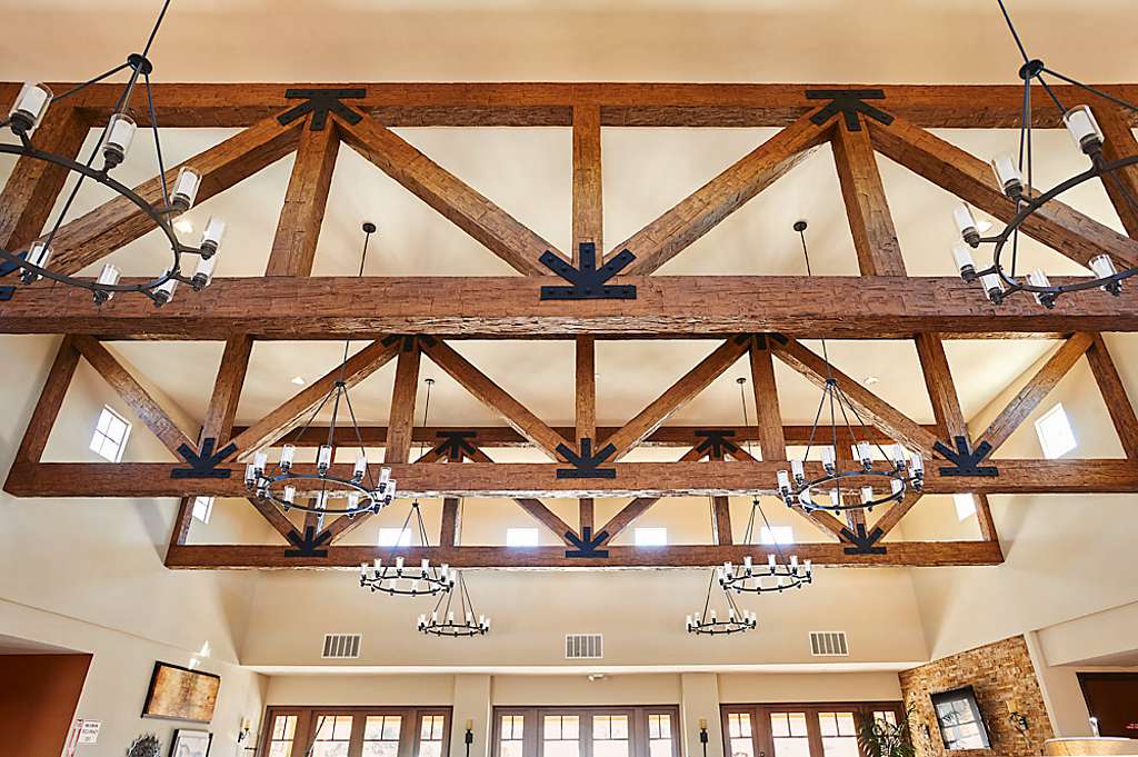
The schematic of a typical triangular chord and strut wood roof truss design is shown in Figure 1. The top chords typically bear loads directly, and the resulting tension and compression load distribution through the struts to the bottom chord accounts for the greater overall load bearing capabilities of the wood truss.

Each intersection will typically have a steel reinforcing plate with stamped barbs pressed into an overlapping position on both sides of the truss which serves to hold the members together. Many modifications of the same basic configuration are possible including, but not limited to, hip, scissors, vault, dual pitch, Polynesian, bow string, dual flat, cantilevered mansard, and almost any architectural design imaginable.
Wood floor trusses follow the same triangular load distributing design but have a long rectangular profile, where the top and bottom chords are parallel to each other. Struts can be spaced to accommodate utility chases, such as air conditioning and heating duct runs for example.
Knowing the expected live and dead loads, the bearing points, overhangs, and other structural factors will allow a manufacturer to calculate the required actual configuration. This process has evolved to the point of using automated manufacturing equipment to fabricate wood trusses to specifications, greatly decreasing labor costs. And by specifying low deflection ratings, such as L/480 or smaller, structural vibrations can be reduced or eliminated as well yielding a very solid response to live load application.


