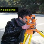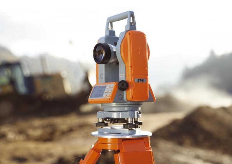
Theodolite is used for measuring horizontal and vertical angles. For this the theodolite should be centered on the desired station point, levelled and telescope is focussed. This process of cantering, levelling and focussing is called temporary adjustment of the instrument.
1. Set the theodolite at Q with vertical circle to the left of the line of sight and complete all temporary adjustments.
2. Release both upper and lower clamps and turn upper plate to get 0° on the main scale. Then clamp main screw and using tangent screw get exactly zero reading. At this stage Vernier A reads 0° and vernier B reads 180°.
3. Through telescope take line of sight to signal at P and lock the lower clamp. Use tangent screw for exact bisection.
4. Release the upper clamp and swing telescope to bisect signal at R. Lock upper clamp and use tangent screen to get exact bisection of R.
5. Read Vernier’s A and B. The reading of Vernier A gives desired angle PQR directly, while 180° is to be subtracted from the reading of Vernier B to get the angle PQR.
6. Transit (move by 180° in vertical plane) the telescope to make vertical circle to the right of telescope. Repeat steps 2 to 5 to get two more values for the angle.
7. The average of 4 values found for θ, give the horizontal angle. Two values obtained with face left and two obtained with face right position of vertical circle are called one set of readings.
8. If more precision is required the angle may be measured repeatedly. i.e., after step 5, release lower clamp, sight signal at P, then lock lower clamp, release upper clamp and swing the telescope to signal at Q. The reading of Vernier A doubles. The angle measured by Vernier B is also doubled. Any number of repetitions may be made and average taken. Similar readings are then taken with face right also. Finally average angle is found and is taken as desired angle ‘Q’. This is called method of repetition.
9. There is another method of getting precise horizontal angles. It is called method of reiteration. If a number of angles are to be measured from a station this technique is used. With zero reading of vernier A signal at P is sighted exactly and lower clamp and its tangent screw are locked. Then θ1 is measured by sighting Q and noted. Then θ2, θ3 and θ4 are measured by unlocking upper clamp and bisecting signals at R, S and P. The angles are calculated and checked to see that sum is 360º. In each case both verniers are read and similar process is carried out by changing the face (face left and face right).