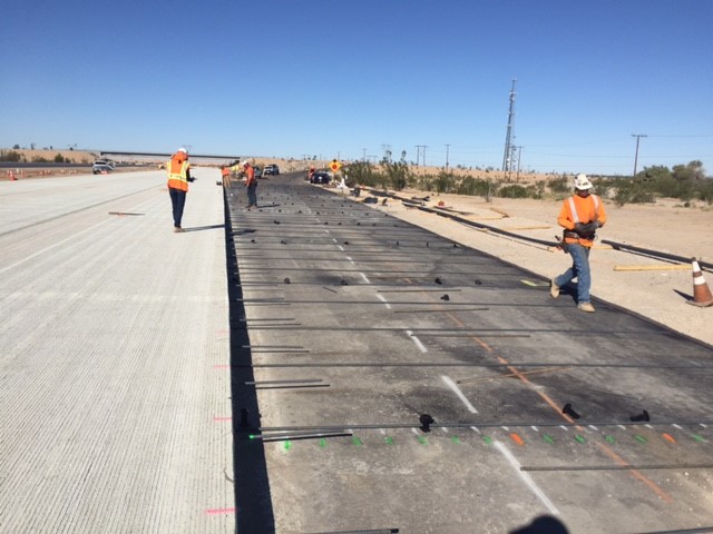
Construction of CRCP is similar to that of other concrete pavement types. Planning and execution are crucial since errors made during these stages can be detrimental to the overall success of the project. It is important to pay special attention to certain details such as the selection and installation of the reinforcement, the carrying out of the construction joints, and so forth. As with any other type of pavement, the base must be finished to ensure a uniform roadbed for the reinforcement supports and construction equipment, as well as, to provide a uniform slab thickness. The base must ensure proper drainage to the slab base interface and be non-erodible to limit the potential of punch-outs. A permeable base fully satisfies these criteria. First, the transverse reinforcement bars are manually placed on metal supports by teams of steel fixers. A sufficient amount of supports will prevent any collapsing under a 250-kg load. Their design must be in accordance with the concrete cover specifications.
Longitudinal reinforcement bars are placed on the transverse ones and then tied to the latter. Generally, it is recommended that longitudinal reinforcement be placed on the upper third section of the slab to limit crack openings. A sufficient amount of concrete cover above the reinforcement is necessary to prevent any corrosion. A minimum spacing of 150 mm between the reinforcement bars is recommended to ensure adequate steel cover. The longitudinal bars may be welded to one another or tied. If tied, the recommended overlap is 25 to 35 bar diameters. The overlaps are usually offset from one lane to the next to ensure they are not all in the same cross section. The free ends of CRCP are exposed to movements mainly caused by temperature differentials. Systems are installed at each end to restrict the movements from the last 100 meters of the slab. Surveys conducted in certain American states concluded that a wide-flange beam provides a cost-effective method for accommodating end movements. In Belgium, anchors made of fixed beams embedded in the base are used. The use of bridge expansion joints is also acceptable. Figure 3 shows the plan of work and a picture of an anchorage beam. Concrete placement for the CRCP is similar to that of the conventional pavement. Desirable results are dependent on the following factors: vibrator adjustment to avoid contact with the reinforcement bars and concrete workability to ensure adequate steel cover. Figure 4 shows pavement placement achieved with a slip form paver. Tie-bars should be placed in longitudinal construction joints to keep slab edges together on either side the joint. Special attention must be paid when forming the transverse construction joints when concrete placement is completed at the end of the day. The Belgians noted incidents of slab blow-ups (9) at construction joint mainly due to the poorer quality of concrete resulting from a delayed or inadequate vibratory compaction on one or both sides of the joint.
The phases subsequent to the placement of CRCP (finishing, texturing, curing, saw cutting of the longitudinal joints and sealing) resemble to that of other slab types.