Bridge Decks
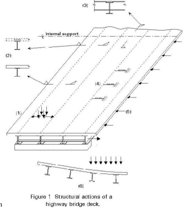
The principal function of a bridge deck is to provide support to local vertical loads (from highway traffic, railway or pedestrians) and transmit these loads to the primary superstructure of the bridge, Figure 1(1). As a result of its function, the deck will be continuous along the bridge span and (apart from some railway bridges) continuous across the span. As a result of this continuity, it will act as a plate (isotropic or orthotropic depending on construction) to support.
Continuity ensures that whether or not it has been designed to do so, it will participate in the overall structural action of the superstructure.
The overall structural actions may include:
· Contributing to the top flange of the longitudinal girders, Figure 1(2).
· Contributing to the top flange of cross girders at supports and, where present in twin girder and cross girder structures, throughout the span, Figure 1(3).
· Stabilising longitudinal and cross girders, Figure 1(4).
· Acting as a diaphragm to transmit horizontal loads to supports, Figure 1(5).
· Providing a means of distribution of vertical load between longitudinal girders, Figure 1(6).
It may be necessary to take account of these combined actions when verifying the design of the deck. This is most likely to be the case when there are significant stresses from the overall structural actions in the same direction as the maximum bending moments from local deck actions, e.g. in structures with cross girders where the direction of maximum moment is along the bridge.
The passage of each wheel load causes a complete cycle of local bending stresses. The number of significant stress cycles is, therefore, very much higher for the deck than for the remainder of the superstructure. In addition, some of the actions of the deck arising from its participation in the overall behaviour are subject to full reversal; an example is the transverse distribution of vertical load between girders. For both these reasons, fatigue is more likely to govern the design of the bridge deck than the remainder of the superstructure.
Shell Structures
Shells are 3d structures constructed on storage tanks or roof for large column area such as indoor stadiums, exhibition halls, theatres, complex churches etc
Classification
Singly curved Double curved Cylindrical shells Singly curved It can be used for rectangular shape buildings, shells represents the roof of the building
Dome storage tank for water and petroleum is example for single curved Doubly curved
For doubly curved structures the super structure should be in hexagonal or circular shape
Cylindrical shape
These ae just modification of pitched roof and frequently employed in modern age construction
It has two types
· North light shell roof
· Barell vault shell roof
Both are different to provide lighting effect in factories
In barell vault ventilation s provided in middle
Off shore platforms
Off shore platforms are self-contained platforms with adequate facilities for drilling, derrick, drilling mud electric power, pumping equipment for the offshore construction these are artificial facilities above the elevation of off shore platforms
Off shore platforms can be classified as
Fixed Off shore platforms
Bottom supported structures Compliant platforms and floating platforms
Construction principles of offshore platforms
Selection of operational criteria
Selection of environment
Environmental factors like
Storming wind
velocity Storming
wave height
Tidal conditions
Before analysis and design of foundation it is necessary to determine the soil characters of the sea shore. Capacities of the available crains will influence the operational activities of platform constructions.
The fixed platforms can be classified into
· Jacket or template structures
· Gravity structures
Comments are closed