Energy efficiency is coming to the forefront in the architecture, as, apart from the significance of a reduced environmental impact and increased comfort for users, the current energy crisis and economic recession has bumped up the importance of the financial cost of energy.
Since the Kyoto Protocol was signed in 1997, governments all over the world have been trying to reduce part of the CO2 emissions by tackling building “energy inefficiency”. In Europe today, the tertiary and housing sectors account for 40.7% of the energy demand, and from 52 to 57% of this energy is spent on interior heating (Willems & Schild, 2008). The new world energy regulations, set out at the European level by the Commission of the European Communities in the First Assessment of National Energy Efficiency Action Plans as required by Directive 2006/32/EC on Energy End-Use Efficiency and Energy Services, (Commission of the European Communities, 2008) indirectly promote an increase in the thickness of outer walls, which, for centuries, have been the only way of properly insulating a building.
The use of vacuum insulation panel (VIP) systems in building aims to minimize the thickness of the building’s outer skin while optimizing energy performance. The three types of vacuum chamber insulation systems (VIS) most commonly used in the construction industry today –metallized polymer multilayer film (MLF) or aluminium laminated film, double glazing and stainless steel sheet or plate (Willems & Schild, 2006) –, have weaknesses, such as the fragility of the outside protective skin, condensation inside the chamber, thermal bridges at the panel joints, and high cost, all of which have a bearing on on-site construction (Baetens et al., 2010).
Apart from overcoming these weaknesses and being a transparent system, the new F²TE³ (free-form, transparent, energy efficient envelope) system that we propose has two added values. The first is the possibility of generating a structural skin or self-supporting façade. The second is the possibility of designing free-form architectural skins. These are research lines that the Pritzker Architecture Prize winners Zaha Hadid, Frank Gehry, Rem Koolhaas, Herzog & de Meuron, among many other renowned architects, are now exploring and implementing.
To determine the feasibility of the new envelope system that we propose, we compiled, studied and ran laboratory tests on the materials and information provided by commercial brands. We compared this information to other independent research and scientific trials on VIPs, such as Annex39 (Simmler et al., 2005), and on improved core materials, such as hybrid aerogels and organically modified silica aerogels (Martín et al., 2008), conducted by independent laboratories like Zae Bayern in Germany (Heinemann et al., 2009), the Lawrence Berkley Laboratory at the University of California (Rubin and Lampert, 1982) or the Technical University of Denmark (Jensen et al., 2005).
After studying the results, we discovered valuable innovative ideas that we exploited to design the new high energy efficient envelope that should outperform the elements now on the market.
The remainder of the chapter is structured as follows. In Section 2 (Research) we explain the rationale of the epistemological study of the system, and how the experimental study combining computer simulations and empirical trials was run. In Section 3 (Experimental study) we describe the design of the proposed envelope system (F²TE³), explaining the solutions adopted in this new system and the improvements on other existing systems. Section 4 (Free-Form, High Energy Performance, Transparent Envelope System (F²TE³) Design) analyses how the F²TE³ system overcomes the weaknesses detected in existing VIP systems. Finally, Section 5 (Conclusion) discusses final conclusions.
Research
Today’s architectural vanguard demands a building system such as is proposed in this research: a lightweight, variable geometry, seamless high energy performance system that also permits the passage of natural light and backlighting.
No system combing all these features exists as yet, and similar systems are not absolutely free form and translucent, are not seamless and/or have a very limited thermal response.
From the viewpoint of energy performance, of the three types of translucent insulations that there are on the market (plastic fibers, gas and aerogel), we found that the insulation that best meets the needs of the new system that we propose is aerogel (Ismail, 2008; Wong et al., 2007).
Aerogel and nanogel (granular silica gel) have four advantages for use as thermal insulation in translucent panels:
a. Transparency: aerogel is comparable to glass in terms of transparency (Moner-Girona et al., 2002). Monolithic aerogel light transparency can be as high as 87.6%, even greater than what some gas-insulated glasses can offer. Granular nanogel offers a greater translucency than any other traditional insulation material (including plastic fiber blankets).
b. Insulation: on top of transparency, it is an excellent insulator. According to published data (Baetensa et al., 2010), the thermal performance of a 70 mm nanogel-filled VIP is better than a 270 mm-thick hollow wall. The insulation values of a 15 mm nanogel-filled polycarbonate sheet are higher than any double glazing of similar thickness.
c. Lightness: aerogel can be three times as heavy as air (Rubin and Lampert, 1982), which means that the panels that employ this material for insulation are very lightweight even though the density of the aerogel that we use as insulation is 50-150kg/m³.
d. Versatility: monolithic aerogel can be shaped as required. Being a nano-sized filling, granular nanogel can be used to fill any chamber.
Let us note that although there are many prototypes and patents (Gibson, 2009; Bartley-Cho, 2006) for the transparent and translucent high energy efficient aerogel-implemented façade panels under study, they are extremely difficult to analyze because there is not a lot of information available and it is not easy to get physical samples of these panels. For this reason, this research has focused on commercial products that are on the market. Most of these products use granular silica aerogel (nanogel).
In the following, we analyze these translucent and transparent panels, setting out their strengths and weaknesses and our findings as a result of this study.
Translucent systems
In this type of systems we have analyzed systems composed of granular silica gel-filled polycarbonate, reinforced polyester and double glazed vacuum insulated panels.
Nanogel-filled cellular polycarbonate panels are the most widespread system on the market. They have the following strengths and weaknesses:
Strengths: Thanks to its low density 1.2g/m³, this is a very lightweight material. It has a high light transmission index ±90% (almost the transparency of methacrylate). It is a lowcost material for immediate use. And, at the competitiveness level, it is the least expensive envelope assembly.
Weaknesses: Durability is low. Most commercial brands guarantee their polycarbonate panels for only 10 years (as of when they start to deteriorate), whereas nanogel has a very high durability. These panels are very lightweight but very fragile to impact. Even though nanogel is an excellent acoustical insulator, the slimness of these panels means that they have acoustic shortcomings.
No more than two types of reinforced polyester panels are commercialized despite the potential of this material. They have the following strengths and weaknesses:
Strengths: Good mechanical properties: glass fiber reinforced polyester resin core composites offer excellent flexibility, compressibility and impact resistance. Good malleability: they could be shaped according to design needs but no existing system offers this option. Durability is good, as there are methods to lengthen the material’s service life considerably (twice that of polycarbonate), like gelcoat coatings or protective solutions with an outer layer composed of a flexible “glass blanket”.
Weaknesses: There is no self-supporting (structural) panel that is standardized and commercialized worldwide. Existing systems have design faults, as they include internal aluminum carpentry or substructures, whereas there is, thanks to the characteristics of reinforced polyester, potential for manufacturing a self-supporting panel (as in the case of single-hull pleasure boats). It is also questionable ecologically, as the polyester is reinforced with glass fiber, which has detracted from its use in building. However, this could change with the advent of new plastic and organic fibers and resins. Economically speaking, reinforced polyester manufacturing systems are very expensive, because either processes are not industrialized or, on the other hand, they rather technology intensive like, for example, pultrusion.
Double glazed vacuum insulated panels (VIP) are still at the prototype stage. Although research and prototypes abound (HILIT+ y ZAE BAYERN, for example) (Fricke, 2005), there are only a couple of commercial brands:
Strengths: Thanks to the combination of vacuum and aerogel insulation (both monolithic and granular), they provide the slimmest and best insulation system in the building world (0.5W/m²K). Transparency levels for some prototypes using monolithic aerogel are as high as 85% for thicknesses of 15 to 20 mm. Additionally, the service life of the glazing and the gel is very similar.
Weaknesses: Product of a combination of vacuum core and double glazing, this component is fragile, especially prone to impact-induced breakages. The high cost of molding glass into complex geometries rules out its use as a free form system. It is a system that depends on substructures and other components for use (Figure 1).
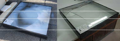
Fig. 1. Brittle fracture of panels tested in the laboratory of the Department of Construction and Technology in Architecture, School of Architecture. (UPM.) E.T.S.A.M.
Findings: After a comparative analysis of over one hundred and forty seven (147) commercial products, and the detailed evaluation of the best eight (8) (Figure 2), we can confirm that fiber reinforced polyester resin panels perform better than the best polycarbonate panels. But these improvements are unable to offset their high production and environmental costs, generating commercially uncompetitive products.
These panels have two unexploited design lines, such as adaptation to new less harmful natural cellulose resins and fibers, the design of insulation for variable geometry translucent skins, or structural improvement for use as a self-supporting component.
As regards energy efficiency, these products offer more energy-saving performance than a 27cm thick traditional wall. With only 7 cm, they have an U value of 0.28W/m²K, which amounts to 7% better energy performance compared to a traditional wall and with 4% less thickness.
Looking at double glazed VIP panels; the data indicate that, although still at the prototype stage, panels like these are the best commercial solution, as they offer the best thermal and acoustical insulation performance and optimal light transmission.
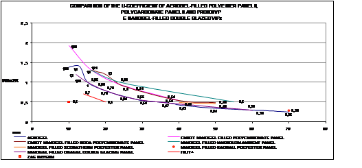
Fig. 2. Comparison of the U-value of the most significant commercial systems and prototypes implemented with an aerogel core existing on the market.
At the acoustical and thermal level, the VIP panel is the best of the envelopes examined, as a 15 mm panel insulates equally as well as a traditional mass wall in terms of energy expenditure (saving). We find that, with a thickness of just 60 mm, this product improves the energy efficiency performance of a 271.5 mm cavity wall.
Transparent systems
All panels implemented with aerogel instead of nanogel are transparent. They have a high solar transmittance and low U value. At present all these systems are non-commercial prototypes, about which little is known. Noteworthy are two aerogel-insulated doubleglazed vacuum insulation panels (VIP):
a. 4-13.5-4 / 21.5 mm double-glazed vacuum panels filled with monolithic aerogel with a pressure of 100hPa1 in the aerogel chamber. The heat transfer coefficient Ug has a U value of 0.7 W/m²K for 14 mm and 0.5 W/m²K for 20 mm compared to the 1.2W/m²K offered by 24 mm commercial nanogel-filled double glazing VIP. This almost doubles the insulation performance of the best commercial translucent panel. Light transmission depends on the angle of incidence, but varies from 64.7 to 87.5%. The sound attenuation index is 33dB for a panel thickness of 23 mm and noise reduction is expected to be improved to 37 dB. The energy saving compared with a dwelling that is glazed with gas-insulated triple glazing (argon and krypton) is from 10% to 20% greater.
b. 10 mm double-glazed vacuum insulation panels with aerogel spacers inside the core (unlikely to be commercialized for another two or three years). The heat transfer coefficient Ug for 10 mm panels has a U value of 0.5 W/m²K. This is the best of all the panels studied so far, where light transmission is equal to glass.
Findings: From the analysis of the transparent panels, VIPs unquestionably come the closest to what we are looking for in this research. The only arguments against VIPs are that they are at the prototype stage. This means that they are not on the market, nor have they been tested, approved or industrialized. All this has an impact on cost. Also being the product of evacuating double glazing panels, VIPs are very fragile. Versatility is limited because, owing to the panel generation process, the maximum dimensions to date are 55 x 55 cm.
From the materials technology analysis, we find that transparent monolithic aerogelinsulated VIPs are the material that best conforms to the goals of transparency, insulation and lightness, provided that we accept that the panels are fragile, non-commercialized prototypes and are not very versatile in terms of size.
Experimental study
Following up the results of the theoretical study outlined in Section 2, we now compare these findings with the results of an empirical experiment and computer-simulations of the real commercial panels to which we had access.
Computer simulation
Existing programs in the market for calculating the energy efficiency are very focused in the pursuit of thermal comfort inside the building. Therefore, we have had to adapt this program’s calculating tools to finish getting results as realistic as possible.
On one side we have had modeled the environment and external environmental conditions of the test site: For this we have used the additional tools of Autodesk calculation programs, such as the Solar Tool (Figure 3) that parameterized the values of sun exposure during the test period, depending on the latitude and longitude of the testing place, or the Weather Tool that transforms all the atmospheric data (wind, temperature, rainfall, percentage of clouds, etc.) in to numerical parameters for use them in the thermal computation.
Fig. 3. Computer simulation: Solar data of March 14, 2010 at 12:00 in Madrid. (Latitude: 40 ° 23’ North, Longitude: 4 ° 01’ West)
On the other hand we has worked with a small-scale models, modelling the real test box, that is a cube of 60x60x60 cm, when such programs are more used to calculate large volumes built, with the adjustments that this has brought. We also have had to model all the panels systems that we tested, with the materials that are composed, in order to include them into our material library.
This whole process of modeling has been done trying to rely on independent test data. We do not want to use the data provided by trademarks, because after all, are the data that we want to verify objectively.
These programs are designed for regulatory compliance (UK and USA, among other). So the programs are oriented to guarantee thermal comfort, through adding contributions from outside air, and even turning on some air conditioning systems without the programmer’s requests. Therefore, in order to get actual results, we had to overcome programming obstacles, disabling predetermined functions in some of the programs.
We used two powerful programs for the computer calculation: DesignBuilder and Ecotect. Although we have worked with both programs at the calculation, at the end we decide using DesignBuilder at the final testing, mainly due to the support the Ministry of Energy of the United States offered to the program and because the data that offered by this program correspond more to those data obtained with trials.
Because of the shortage of information about aerogel and the impossibility of acquiring a sample, we decided to use the Design Builder program to conduct a trial by computer simulation under the same environmental conditions as the empirical trials run on the other panels. Figure 2 describes the behavior of a 25 mm aerogel sheet. We find that the test space has a uniform inside temperature of between 18 and 37 ºC.
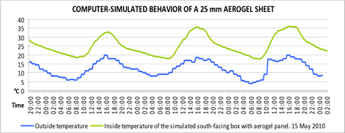
Fig. 4. Computer simulation for a 25mm thick sheet of silica aerogel with density 50150kg/m³ over 78 hours.
Figure 4 describes the behavior of a 25 mm Aerogel panel. We checked that the temperature inside the test space is evenly maintained between 18 and 37 °C. The curves at the loss periods are stretched, which means that this is a good thermal insulation, as it loses energy at a very long term and gradually.
Empirical trials
The trials are designed especially to examine the energy performance of the material. These trials were run at the Department of Building and Architectural Technology of the UPM’s School of Architecture on boxes with an inner volume of 60 x 60 x 60 cm, insulated with 20 cm of expanded polyurethane. One of the box faces is left open by way of a window. The study elements are placed in this opening using a specially insulated frame. The trial involves exposing two such boxes to a real outside environment to study their behavior. The two boxes have two different windows: one is fitted with 6+8+6 double glazing with known properties as a contrast element and the other is fitted with the panel that we want to study. Data loggers are placed inside each box for monitoring purposes to measure and compare their inside temperature. The boxes are also fitted with a thermal sensor on the outside to capture the temperature to which they are exposed. The boxes are set in a south-facing position as this is the sunniest exposure (Figure 5).
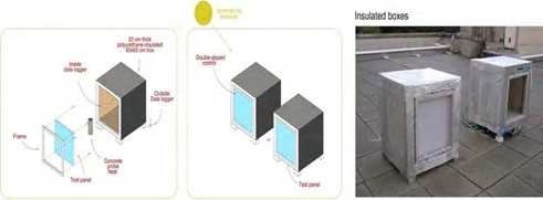
Fig. 5. Energy performance testing of the UPM system based on the hot box method
We ran twenty-eight (28) temperature-measuring trials using this system, and compared the performance of different thicknesses of commercial panels with 6+8+6 double glazing. Four (4) of these panels deserve a special mention.
Trial-1: 16mm nanogel-filled Cabot Lexan Thermoclear polycarbonate sheets (PC sheets)
Results: There is on average a 2.5 ºC improvement in thermal properties over the commercial Climalit double glazing (which is 5 mm thicker than the panel) at night, and it insulates almost 6ºC more than double glazing exposed direct solar radiation (Figure 6).
The fast enough rise of the curve at time of the thermal capture (day) is very similar in the two samples tested and compared (in the study panel and in the double glazing window sample probe), which means that their qualities are very similar solar collection, but there is a delay at the temperature increase with a difference of 24 minutes for the polycarbonate panel filled with nanogel, between one rise in the temperature and the other (between days). This confirms the market values in which, although showing a similar response of the double glazing, the polycarbonate panels filled with nanogel of similar thickness, usually have a small improvement if we compared them with a double glazing window.
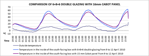
Fig. 6. Trial 1. Sample tested: (600x600mm of side) Policarbonate Panel of 16mm thick filled with nanogel. The test was made from the 9th (19:00 h) to 12 (15:00 h) in April 2010. At the
E.T.S.A.M. School of Architecture & School of Computing (UPM) Spain
With the night loss, the difference between items is growing. The loss curve of the plate that is filled with nanogel is much more horizontal (which shows a U-value lower) than the loss curve of the sample window, leading to reduce the energy loss of the panel, and keeping the heat within the interior volume for more than 75 minuts and with a temperature that never is down the 10 °C although the outside temperatures was in the order of -4 °C.
These results support that a 16 mm polycarbonate panel filled with nanogel offers some benefits (although similar) than those offered by the double glazing of 20 mm (6+8+6).
Trial-2: 25mm nanogel-filled Cabot Lexan Thermoclear (triple-wall) polycarbonate sheets (PC sheets)
Trial-2: 25mm nanogel-filled Cabot Lexan Thermoclear (triple-wall) polycarbonate sheets (PC sheets).
Results: There is on average a 2 to 3 ºC improvement in thermal properties over the commercial Climalit double glazing (which is 5 mm thinner than the panel) at night, and it insulates 15 to 20 ºC more than double glazing exposed to direct solar radiation (Figure 7).
The solar collection curves are very different in this graph (figure 7). While in the double glazing, the rise of the curves is very fast and in 150 minutes (two hours) the curve has risen to nearly its maximum inside temperature, the panel filled with nanogel creates a flatter curve that marks a more homogeneous rise, and it takes 300 minutes (five hours) to reach its maximum inside value. Furthermore, there is a heating delay of 120 minutes for the box where we are testing the polycarbonate sheet filled with nanogel. All of this clearly shows the best performance of this panel versus the double glazing in daytime solar collection.
The loss curves at night make a similar trend, a difference of 360 minutes, six-hour delay between the thermal losses of 25 mm panel filled with nanogel and the double glazing window. A flat graph denotes a small U-value. Also noteworthy is that the graph of the polycarbonate panel filled with nanogel oscillates in a strip of between 25 ºC and 40 ºC as
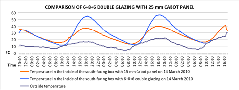
Fig. 7. Trial 2. Sample tested: (600x600mm of side) Policarbonate Panel of 25mm thick filled with nanogel. The test was made from the 14th (20:00 h) to 17 (16:00 h) in May 2010. At the E.T.S.A.M. School of Architecture & School of Computing (UPM) Spain
the maximum internal temperature inside the box, whereas the graph of the double glazing is between 55 ºC and 10 ºC.
These data show that increasing the insulation thickness leads a heat improvement of the system that is almost directly proportional to the thickness. With a increase of the 36% of the thickness, we obtained a thermal efficiency of 33% (20 °C improvement) in the solar collection and (5 ºC improvement) in night losses.
Trial-3: Bayer Makrolon Ambient S2S-25 sheet. 25 mm nanogel-filled twin-wall polycarbonate panel
Results: Behavior is very uniform. We get a 3 ºC improvement in thermal properties over the commercial Climalit double glazing, which is 5 mm thinner, at night, and it insulates 5 ºC more than double glazing exposed to direct solar radiation (Figure 8).
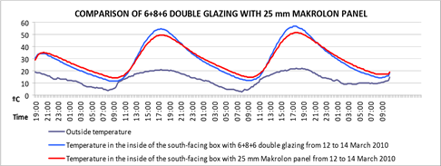
Fig. 8. Trial 3. Sample tested: (600x600mm of side) Policarbonate Panel of 25mm thick filled with nanogel. The test was made from the 12th (20:00 h) to 14 (16:00 h) in March 2010. At the
E.T.S.A.M. School of Architecture & School of Computing (UPM) Spain
The solar collection curves (day) are very similar in both the study panel as in the double glazing sample and ascend quickly. Even though that thermal uptake quality are very similar in both elements, there is a delay difference of the temperature increase inside the box where the polycarbonate panel is tested of 45 minutes over the double glazing window.
At night loss the panel filled with nanogel is more flat from the start, marking quick differences with the double glazing. This trend lasts all night which denotes a small U-value and keeps the heat within the interior volume of the box over 80 minutes.
This confirms the market values, which showed that despite having the same thickness of panel (25 mm) and use the same Cabot nanogel, there are big difference between the Makrolon panel and the Lexan Thermoclear panel.
Trial-4: 70 mm Okagel Okalux VIP Panel: Nanogel-filled vacuum insulation panel Results:
Temperature is homogeneous ranging between 17 to 32ºC, and there is an almost constant difference of from 3 to 10ºC compared with double glazing (Figure 9).
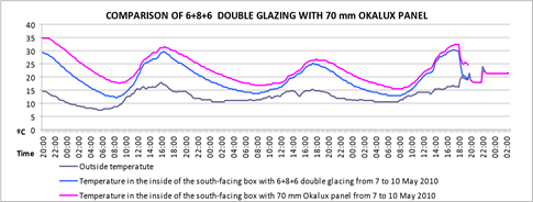
Fig. 9. Trial 4. Sample tested: (600x600mm of side) double glazing Panel/window of 70mm thick filled with nanogel. The test was made from the 7th (20:00 h) to 10 (16:00 h) in March 2010. At the E.T.S.A.M. School of Architecture & School of Computing (UPM) Spain
These four trials were evaluated and compared with the computer-simulated aerogel data (Figure 10) and data from the theoretical study. We found that, like the data output by the theoretical study, the real trials suggest that the materials behavior is suitable for designing the new envelope system. The very flat loss curves in the plot describe a very low U value. In terms of capture, there is a thermal difference of almost 30ºC between the Okagel (VIP) panel and the worst of the tested panels. The difference between Okagel and the bestperforming panel is almost 10 ºC in terms of loss and capture. We have confirmed the experimental datum that likens the behavior of the Okagel panel to that of the computersimulated aerogel.
From our computer-simulated experimental study, the data on organic aerogels supplied by the CSIC and the University of Barcelona, and the data from trials run at the University of Denmark on envelopes implemented with monolithic silica gels and the empirical trials conducted in this research, we arrive at the following conclusions:
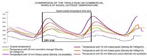
Fig. 10. Comparison of empirical data of commercial systems with computer simulation of 25 mm thick sheet of silica aerogel with density 50-150kg/m³ over 78 hours (temperatures inside the test boxes)
The best-performing panel from the energy saving viewpoint is 70 mm Okalux that has thermal differences with respect to the other panels ranging from 5 to 20ºC. Also striking is the disparity in the results of the 25 mm and 15 mm Cabot panels with thermal differences of 15ºC.
Although the specific temperatures and factors on each test day differed from one trial to another, the 70 mm nanogel-filled Okalux VIP panel performed similarly to the 25 mm aerogel sheet.
These are key data that are useful for designing a new lightweight, slim, high energy efficient, light-transmitting envelope system, providing for seamless, free-form designs for use in architectural projects.
Free-Form, High Energy Performance, Transparent Envelope System (F²TE³) design
The proposed component has better properties than double glazing VIP and reinforced polyester panels (Okalux and Kallwall) separately, as it combines the properties of the two to generate a new system and solve the problems specified earlier.
This section will present the “Proposal for a Free-Form, Transparent, Energy Efficient Envelope System (F²TE³)”, and will explains the details of the new system, materials of construction, its size and overall value. Also shows the way to manufacture our system and the On-site assembly of the new system. We make a special reference of how the F²TE³ response to the weaknesses of VIP systems. Finally, we study the tests to determine the level of energy efficiency by calculation by computer.
Proposal for a Free-Form, Transparent, Energy Efficient Envelope System (F²TE³)
We propose a free-form design envelope system fabricated with cellulose fibers and polyester resin (or acrylic-based organic resin), and a vacuum core insulated with monolithic aerogel at a pressure of 1hPa. Being a self-supporting component, the system can perform structural functions, and seams between panels are concealed by an outer coating applied in situ (Figure 11).
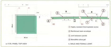
Fig. 11. F²TE³ Envelope Profile Design
Materials: The optimal materials are: (a) a natural cellulose fiber-reinforced epoxy resin matrix with similar performance to E-type glass fiber, with an outer gelcoat coating to protect it from external agents for the outer skin, on which the panel’s resistance, protection and variable geometry depends, and (b) a thermal/acoustical insulation component composed of a monolithic silica gel-filled vacuum chamber.
Dimensions:
Based on tests run at the University of Denmark, we have to take into account the sol-gel process drying times required for the monolithic silica gel to generate a crystalline structure, the percentage of breakages due to size and, above all, the fact existing autoclaves are able to generate monolithic gel pieces no larger than 55 x 55 cm. The panel sizes will be 60 x 60 cm (length/width), and panel thickness will depend on whether the structure is self-supporting or a simple envelope. For modeling purposes, however, we have studied a 25mm thick panel, composed of two sheets of 3 mm thick reinforced resin and a vacuum core filled with monolithic silica gel (Figure 12).
The weight per unit of surface area will be from 15 to 7 kg/m2. Although dimensions could vary, the sheet width will be no greater than 600 x 600 mm and the minimum admissible flexion radius will be approx. 4000 mm.
Specifications:
Light transmittance, τD65: from 59% to 85% approx.
UV absorption: approx. 20%
Total energy: approx. 61%
Horizontal and vertical U-value: 0.50 W/m2 K
Thermal conductivity coefficient: 0.01 W/m K, estimated
Possible heat-and humidity-induced dilation: 3 mm/m approx.
Operating temperature: -70 to +80 °C
Weighted sound reduction value: estimated at 26-45 dB
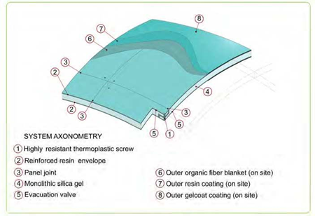
Fig. 12. F²TE³ system axonometry
System specifications
The F²TE³ is composed of the dry-seal connection of previously designed male and female edged panels (two female sides and two male sides on each panel that fit together seamlessly). Once the construction is in place, it is given an outer coating of fibers and resins and finally a gelcoat coating to protect the assembly from external agents.
Manufacturing and on-site assembly (Figure 13):
The off-site manufacturing process is composed of the following phases:
a. An easy-to-use, reusable and ecological molding process. As this does not have to be a structural mold, it can be made of compressed and sanded sheeting arranged according to the panel design.
b. The same mold is used to generate the two panel ends and its walls.
c. The walls are adhered to one of the ends using resin, and the assembly is filled with silica gel, where the panel itself acts as a mold to shape the monolithic silica gel inside the chamber.
d. Sol-gel technology is used to generate the aerogel inside the panel using an autoclave.
e. The top end is adhered to the panel using resins.
f. The panel is evacuated to a pressure of 1hPa inside the chamber.
g. The panels are transported separately to the site. Scaffolding and props are then used to assemble in situ the panels making up the façade. The panels are screwed together using highly resistant transparent thermoplastic screws.
The system should be manufactured under adequate health and safety conditions.
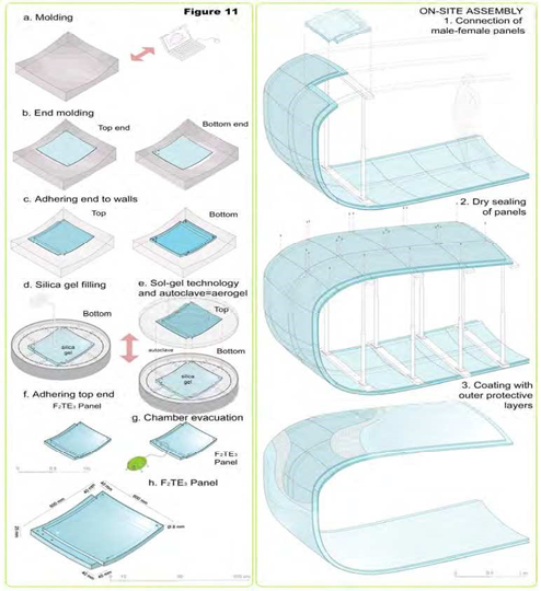
Fig. 13. Manufacturing and On-site assembly
Testing
A F²TE³ system with a thickness of 25 mm has been computer simulated to examine its energy-saving behavior compared with a computer-simulated aerogel envelope of the same thickness (Figure 14).
As shown in Figure 12, although the plots are displaced, the F²TE³ system returns a result very close to what would be achieved with monolithic aerogel without a barrier envelope (not feasible due to aerogel hydroscopy). Even with a barrier envelope, F²TE³ performance
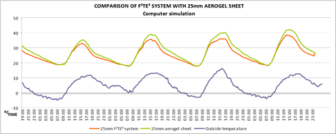
Fig. 14. Comparison of a computer simulation of a 25mm thick sheet of silica aerogel with a density of 50-150 kg/m³ with the F²TE³ system over 96 hours.
almost equals aerogel in terms of heat loss, with a very similar flat curve, where the U value is very small, but results for capture are worse at over 5ºC higher.
F²TE³ response to the weaknesses of VIP systems
Most studies conducted in the field of VIP elements (VIS) (Mukhopadhy et al., 2011) determine that there are four key obstacles to the use of these systems in the building industry: a) fragility of the outer skin, b) thermal bridging at panel edges and joints, c) vacuum chamber moisture permeation, and d) price. On top of these weaknesses, there is the added obstacle of a single element having to provide transparency and energy efficiency, plus a new demand from vanguard architecture for generating free forms by means of monocoque systems.
Theoretically, the new F²TE³ overcomes all the above objections raised against VIPs, offering the added values of transparency and free-form design:
a. Fragility of the outer skin: As the new system has to be a transparent and selfsupporting structure, we have replaced the fragile outer barrier elements, such as a metallized polymer multilayer outer skin, double glazing and thin stainless steel sheets, with an element composed of highly resistant reinforced fibre resin.
b. Thermal bridge at panel edges and joints: Commercial panels are not designed to be assembled to form seamless elements. The new system that we propose is purposely designed to generate monocoque elements through a system of male and female panels. This system eliminates the thermal bridge between the panels (see Figure 15).
c. Moisture in the vacuum chamber: One of the key problems of VIP systems is condensation forming inside the chamber. Although some studies estimate that the hydroscopic silica smoke is capable of absorbing most of the minimal amount of condensation that forms without compromising its load-bearing or thermal capacities, the fact is that humidity inside the chamber ends up turning the monolithic aerogel opaque. F²TE³ solves this problem by modifying the barrier thickness. The outside face is 3 mm thick compared with the inside face that should have thicknesses ranging from at least 6
to 8 mm to prevent condensation forming inside the chamber. We used the COAG’s memorias2 program to plot the condensation graph of the new envelope, and the resulting sections are shown in Figure 16.
F²TE³ has a water vapour permeability value of 0,3 g/m²d (for 3mm thickness) less than some commercial VIP panels (0,5 g/m²d).