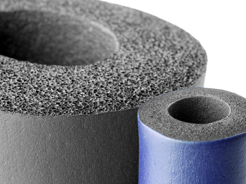
Mineral fiber products are the most common group of thermal insulations currently in use. Heat transfer in these materials has been the subject of extensive investigations thanks to their numerous and varied applications as building and industrial insulations. Early studies addressed the problem of energy transport in terms of a simple theoretical model. They showed that gas conduction and radiation are the two dominant modes of heat transfer in fibrous insulations [Verschoor et.al. (1952), Bankvall (1974), Bhattacharyya (1980), and Larkin and Churchill (1959)].
Subsequent theoretical studies have been devoted to the solution of the radiative transfer equation in semi-transparent absorbing and isotropic scattering media. Tong and Tien (1980) developed analytical models for radiation in fibrous insulations. They (1983) modeled the radiative heat transfer by the two-flux and linear anisotropic scattering solutions compared well with experimental values. Transient heat transfer was also studied in other works Tong et. al. (1985-1986), and McElroy (1986).
Lee (1986, 1988, and 1989) and Lee and Cunnington (1998, and 2000) proposed radiation models which rigorously account for fiber morphology and orientation. Later models (1997, and 1998) used the radiative properties of the fibers. The contribution of radiative heat transfer through foam insulation was examined by Glicksman et al. (1987). Langlais et al. (1995) worked with the spectral two-flux model to analyze the effect of different parameters on radiative heat transfer. Zeng et al. (1995) developed approximate formulation for coupled conduction and radiation through a medium with arbitrary optical thickness. Daryabeigi (1999) developed an analytical model for heat transfer through high-temperature fibrous insulation. The optically thick approximation was used to simulate radiation heat transfer. He (2003) also modeled radiation heat transfer using the modified two-flux approximation assuming anisotropic scattering and gray medium.
Asllanaj, Milandel and their coworkers (2001, 2002, 2004, and 2007) studied different aspects of radiative-conductive heat transfer in fibrous media and made great contribution to the progress of this field. Yuen et al. (2003) used measured optical properties, the Mie theory, and the zonal method, to predict the transient temperature behavior of fibrous insulation.
Nisipeanu and Jones (2003) applied the Monte Carlo method to model radiation in the entire coarse fibrous media. Not only is this method computationally demanding, it also fails to take into account the contribution of conduction in radiation heat transfer. Moreover, it assumes random distribution of fibers in the media, while in reality the majority of fibers are oriented perpendicular to the heat flux.
The Monte Carlo method is essentially a time consuming process. As such, it has not been widely applied to model radiation heat transfer in previous studies. In the present work, however, distribution factors have been used to expedite computation. The number of calculations during each iteration is considerably reduced by this method. Radiation is coupled with conduction via the source term in the heat conduction equation. In addition, the present method considers fiber orientation perpendicular to heat flux, which is a more logical assumption than random orientation of fibers.
Physical model and mathematical formulation
As depicted in Fig. 1, the analytical model assumes that insulation is confined between two horizontal plates, having temperatures TH (top plate) and TC (bottom plate). Thus, the heat flux vector is aligned with the local gravity vector in order to eliminate free convection. Air inside the material is considered to be stagnant and dry and at atmospheric pressure. The heat transfer mechanism in fibrous insulations therefore includes solid conduction, gas conduction and radiation and the total heat flux is given by the sum of radiative and conductive heat fluxes:

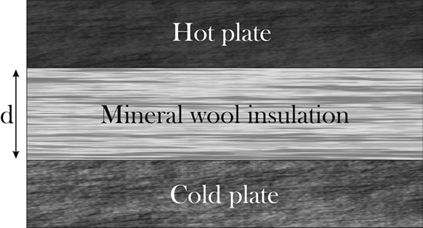
Fig. 1. Problem geometry
The steady state energy equation for a one-dimensional heat transfer is given by:
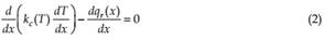
where k Tc( ) is the effective thermal conductivity of the medium. The semi-empirical relation suggested by Langlais and Klarsfeld (2004) was used to model k Tc( ) for insulations made of silica fibers. The relation is based on experimental data obtained from a Guarded Hot Plate apparatus (Saint Gobain Research Center):

where ρ is the bulk density of the fibrous insulation, and Tm is the mean temperature of the medium. This relation takes into account both air and fiber conduction as well as the contacts between fibers.
Radiation modeling
Radiation heat transfer through the medium considered in this work involves absorption, emission and scattering. The radiation modeling introduced here is based on the Monte Carlo Ray Trace (MCRT) method [Modest (2003), and Mahan (2002)], a statistical approach in which analytical solution of the problem is bypassed in favor of a numerical simulation, which is easier to carry out. The probabilistic description of radiation heat transfer by the MCRT method [Modest (2003), and Mahan (2002)] is based on the photon view of thermal radiation. The general approach in the MCRT method is to emit a large number of energy bundles from randomly selected locations on a given surface element and then to trace their progress through a series of reflections until they are finally absorbed on a surface element [Mahan (2002)]. As radiation heat transfer is a three dimensional phenomenon, direct simulation is utilized to model radiation heat transfer in fibrous media.
Equation (2) is a one-dimensional energy equation therefore it should be coupled with one dimensional radiative heat transfer equation. Accordingly, results for a three-dimensional direct modeling need to be averaged out into a one-dimensional media. The radiative heat flux term in Eq. (2) indicates a radiative heat source. Therefore radiative heat sources have to be found in parallel planes along the x-axis. The one-dimensional radiation heat transfer equation for computing these radiative heat sources can be written as:
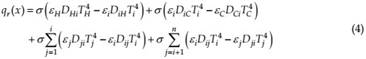
where i indicates the plane number at the location of x, H, and C indicate the hot and cold bounding plates. DHi and DCi are the the radiation distribution factor (RDF) of the hot and cold bounding plates to the fibers’ plane respectively, DiH and DiC are the RDF of the fibers’ plane to the hot and cold bounding plates respectively. Dij and Dji are the RDF between different elements within the media. Dij is defined as the fraction of the total radiation emitted diffusely from element i and absorbed by element j, due to both direct radiation and to all possible diffuse and specular reflections within the enclosure [Mahan (2002)].
The first term on the right hand side of Eq. (4) represents the radiative heat flux emitted by the hot bounding plate and absorbed by the fibers in plane i, the second term represents the radiative heat flux emitted by the fibers in plane i andabsorbed by the cold bounding plate, and the third and fourth terms represent the resultant interaction radiative heat flux between the fibers in plane i and other fibers within the media in different planes.
From Eq. (4), it is clear that the radiative distribution factor is required for two different cases; RDF among fibrous planes and the RDF of the fibrous planes to the boundary plates. Hence, the problem is to find the radiation distribution factor for these two cases as a function of relative distance.
Application of the reciprocity relation, Eq. (5), readily gives the distribution factors from other planes to the source plane. A similar procedure is adopted to compute the RDF of the fibers to the bounding plates.

where εi and εj are the emissivity of the fibers i and j. Ai and Aj are the surface areas of fibers planes i and j.
It is assumed that for the limited temperature range considered, the radiative distribution factor is not a function of temperature. Therefore, it is possible to compute the RDF of the fibers for the mean temperature properties and it is not required to recompute distribution factors in each iteration procedure.
In addition, as the fibers are distributed randomly in the plates normal to the heat flux, the RDF of the fibers is not a function of their position but of their relative distance. For instance it is possible to say that Dij for fiber i has the same value for all fibers j which are located at the same distance from fiber i. Therefore, it is only required to compute one fiber’s RDF in the assumed simulated cylindrical media and the results can be utilized for the entire domain. To compute the RDF of the fibers to the plates, it is possible to compute the RDF of the plate to the fibers and apply the reciprocity rule (Eq. 5).
The following procedure is adopted for computing the RDF of the fibers:
A simulated cylindrical media with a specific radius and infinite height is assumed in which fibers are randomly located parallel to cylinder’s axis as shown in Fig. 2. It is assumed that the fibers are distributed randomly with a uniform distribution in the media and the number of fibers per volume in the media is a function of the material’s porosity. As the average fiber diameter and the porosity of the material are measurable, it is possible to define the number of the fibers in the defined cylinder. The radius of the assumed cylinder should be long enough so that no emitted energy bundle can escape the media. This length is directly related to the optical thickness of the fibers.
Figure 3 shows the flow chart of the MCRT for the given problem. RDF of the fibers has a rapidly decaying exponential behavior. Hence the cylinder defined for the determination of the RDF could have a short diameter as compared to the thickness of the real fibrous media.
This considerably reduces simulation time.
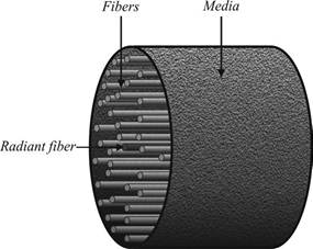
Fig. 2. Simulated cylindrical fibrous media for computing the radiation distribution factor of the fibers
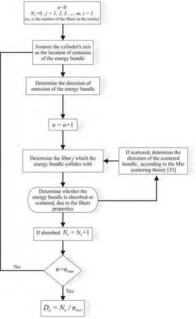
Fig. 3. Flow chart of the MCRT method for computing the fibers radiation distribution factor The same procedure can be used to compute the distribution factor of the fibers to the bounding plates. In this case the radiant fiber is assumed to be at the center of a semi cylinder, on the boundary surfaces, as shown in Fig. 4. The plate is assumed to be opaque. The RDF of the plate to the fibers is determined by direct Monte Carlo simulation, and by employing the reciprocity rule the RDF of the fibers to the plates can readily be computed. Figure 5 shows the flow chart of the MCRT for the given problem.
The Mie scattering phase function is applied to determine the direction of the scattered radiant from fibers [35]. The Mie phase function depends on the mean diameter, index of refraction of the fibers and the prominent wave length of the media.
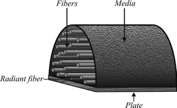
Fig. 4. Simulated semi cylindrical fibrous media for computing the radiation distribution factors of the fibers to the plate
Computational procedure
Considering the nature of the problem which involves combined radiation and conduction equations; the solution of the coupled equations involves an iterative procedure. Therefore, in every iterations the conduction and radiation equations should be solved. Since RDFs need not be recomputed in every iteration, the computations are considerably more efficient as compared to those methods in which radiation is fully coupled (such as: discrete ordinate method, spherical harmonics, or zonal method).
To solve the energy equation, the simple implicit (Laasonen) method [Anderson (1984)] is used to discretize implicit time and space derivatives. This method has a first-order accuracy with a truncation error of O[Δτ, (Δx)2] and is unconditionally stable. Several grids were tried with 500, 1000, 2500, 5000, and 10000 nodes; comparing the results obtained showed that the 5000 node grid was sufficient for this case study.
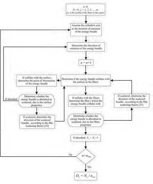
Fig. 5. Flow chart of the MCRT method for computing the fibers radiation distribution factor to the plate
The flow chart of the corresponding method is given in Fig. 6. The iterations continue until convergence of the iterative procedure. The convergence criterion is based on the rms of the difference between temperatures of two subsequent iterations as defined below:
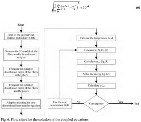
where TjP indicates temperature inside the media at location i and at iteration p, and n indicates the number of grid nodes.
The real condition of the Heat Flow Meter (HFM) apparatus was used in the proposed model.
The boundary temperatures were 0C and 20C . The thickness of the media was taken as
5cm . The experiments conducted at Building and Housing Research Center (BHRC) showed that the mean diameter of fibers from samples studied was seven microns. The averaged index of refraction for glass is considered to be 1.49 1 104i , where i is imaginary unit (derived from the Hsieh and Su, [Hsieh (1979)]. As the mean temperature is 283K, from Wien’s displacement law [Siegel, and Howell (2002)], the wavelength from which the largest amount of radiative energy is transmitted is 10m . Therefore, the radiative properties are the same as the properties proposed by Roux [Roux (2003)] in this wavelength. A boundary surface emissivity of 0.9 (as declared by Netzsch, the manufacturer of the HFM apparatus) is used for these computations.
Discussion
Numerical results
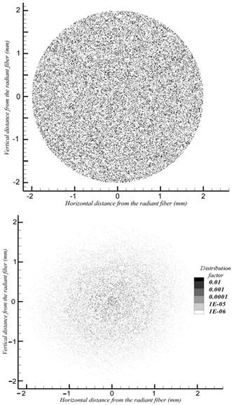
Figure 7(a) shows the cross section of the simulated fibrous media for a density of
500(kg /m3) and Fig. 7(b) shows the cross section contour of the radiation distribution
 (a)
(a)
(b)
Fig. 7. (a) Cross section of the simulated cylindrical fibrous media for 500kg /m3 ,
(b) Cross section contour of the radiation distribution factor for 500kg /m3
factor for the same density. Figure 7 clearly shows that the radiative distribution factor decays rapidly, obviating the need for determination of the RDF for the entire media.
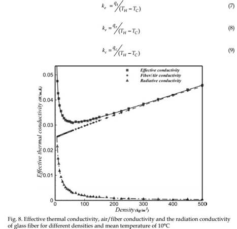
The results of the effective thermal conductivity, ke, (Eq. (7)), radiative conductivity, kr, (Eq. (8)), and the air and glass fiber conductivity, kc, (Eq. (9)) computed with the current method for different densities between 5 and 500(kg /m3) are shown in Fig. 8.
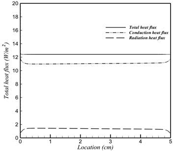
Total heat flux, conduction and radiation heat flux of fiber glass under steady state condition for 50kg /m3 and 7.5kg /m3 according to the position in the medium, are shown in Figs. 9(a) and 9(b), respectively. As is seen in Fig. 9(a, b) total heat flux for 7.5kg /m3 is 33.8% greater than the total heat flux for the 50kg /m3 . In addition, the radiation heat flux is 12.6% of the total heat flux for 50kg /m3 , and 45.2% of the total heat flux for 7.5kg /m3 .
(a)
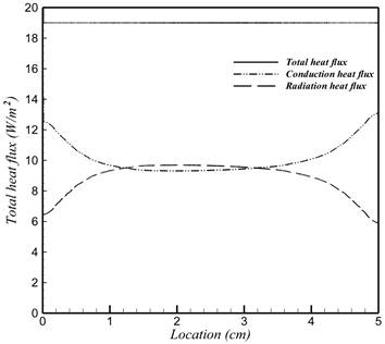
(b)
Fig. 9. Total heat flux, conduction and radiation heat flux of fiber glass at steady state condition and mean temperature of 10°C, according to the position in the medium: ![]()
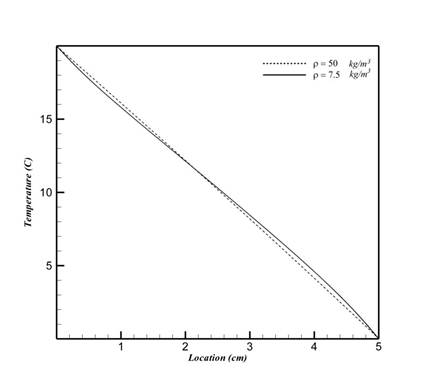
![]() Fig. 10. Temperature profiles within the medium for mean temperature of 10°C, and
Fig. 10. Temperature profiles within the medium for mean temperature of 10°C, and
Experimental measurements
A large number of experiments were performed at BHRC on mineral wool insulations for determination of thermal conductivity and microstructural analysis. The stereo-microscopy observations of the samples showed that most of the fibers are oriented parallel to the faces and the boundaries (Fig. 11). Thus, the direction of heat flow is perpendicular to the direction of the majority of fibers. Accordingly the model’s assumption of parallel cylindrical fibers is well justified.
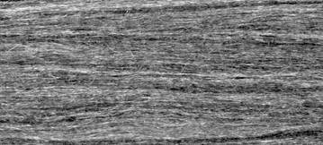
Fig. 11. Stereo micrograph of glass wool
Scanning electron microscopy (SEM) showed that the diameter of the fibers is 6.2-8.8 microns. The mean diameter of fibers determined with SEM is about 7 μm. As the diameters of these fibers are much smaller than their length, the length can be assumed infinite in the model in comparison to the diameter.
The effective thermal conductivity of more than 300 different samples of glass fiber products with densities ranging from 6 to 120 kg /m3 were measured. The conductivity measurements were carried out at BHRC with a heat flow meter (HFM) apparatus according to EN12667 (2001). The HFM apparatus used is a single-specimen symmetrical device that consists of two heat flow meters and allows the detection of the heat transfer rate on both the hot and cold sides of the specimen. The cold and hot plate temperatures were set at 0C and 20C , respectively. The samples were dried in a ventilated oven and then brought into equilibrium with laboratory air temperature. To prevent moisture from migrating to the specimens during the test, specimens were enclosed in a vapor-tight envelope. The accuracy of thermal conductivity determination was better than 3%. Measurement repeatability was found to be better than 1% both when the specimen was maintained in the apparatus and removed and mounted after a long interval. For bulk density determination the accuracy in the measurements of specimen length, width, and thickness were better than 1%. The maximum uncertainty in measured specimen thickness due to departures from a plane was 0.5%. The maximum uncertainty in the determination of specimen mass was 0.5%.
Comparison of numerical and experimental results
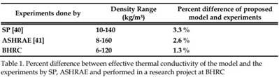
The numerical model was validated by comparing the predicted effective thermal conductivity with measured data from the research at BHRC, those obtained in Technical Research Institute of Sweden (SP) [Jonsson (1996)], and those presented in ASHRAE handbook [ASHRAE (1997)] for fibers with 5.6 μm diameter.
The comparison of the effective thermal conductivity of glass fiber having different densities obtained from the proposed model and the experimental results, are shown in Fig. 12. It can be seen that in lower densities, where radiation is dominant, experimental results conform excellently to the model predictions. Table 1 shows the percentage of difference between the results of the proposed model and the experimental results. The model predictions are in good agreement with measurement results.
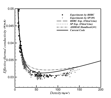
Fig. 12. Comparison of effective thermal conductivity between current method and experimental results of SP [Jonsson (1996)] and ASHRAE [ASHRAE (1997)] and those obtained in a research project at BHRC
Conclusion
This chapter introduces a new numerical modeling of steady state heat transfer for combined radiation and conduction in a fibrous medium for the prediction of the effective thermal conductivity. Radiant heat transfer in mineral wool insulations is modeled by the statistical-based Monte Carlo method. A finite difference approach has been developed to solve the governing coupledradiation and conduction heat transfer equations. The numerical model was validated by comparison with effective thermal conductivity measurements at different densities. The proposed method is easy to code and computationally efficient. The model is able to sort out individual contributions of conduction and radiation heat transfer mechanisms in these materials.

Comments are closed