A layout of the complete surface of a three dimensional object on a plane surface is called its development or pattern. Development is a term frequently used in sheet metal work where it means the unfolding or unrolling of a detail into a flat sheet called a pattern
There are three methods of pattern development; (i) Parallel line, (ii) Radial line and (iii) Triangulation.
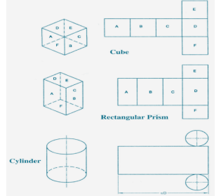
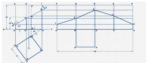
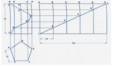
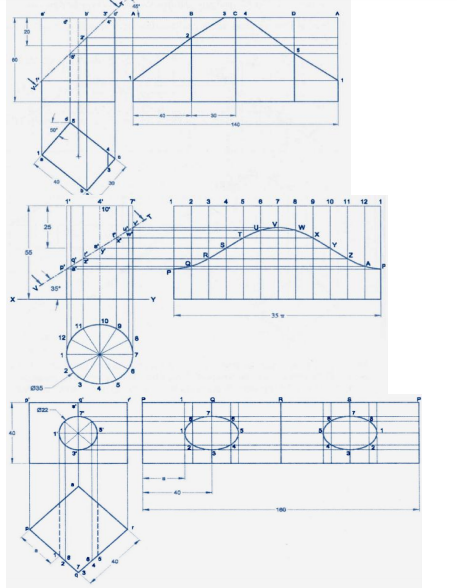
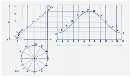
Parallel Line Method:
This method can only be used to develop objects (or parts thereof) having a constant cross-section for their full length, for example, prisms and cylinders and related forms. Parallel lines, parallel to the axis of the detail, are shown on a view which shows them as their true lengths.
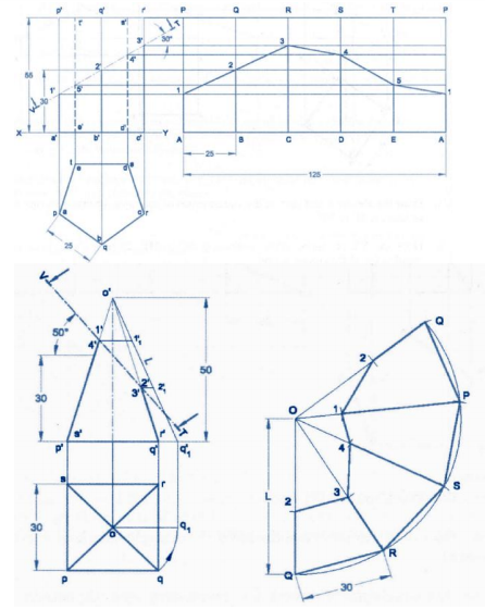
1. After drawing the given views, determine the view in which the right section of the solid appears as an edge view. Here it should be noted that top views of right prisms and cylinders are equivalent to their right sections will have to be found in the form of an auxiliary view.
2. Layout the stretch-out line of the development parallel to the edge view of the right section.
3. Locate the distance between lateral comer edges by measuring from the true size views in the right section and then transferring these measurements to the stretch-out line. Name their points.
4. Draw the lateral fold lines perpendicular to the stretch-out line through the points already plotted.
5. The development should be commenced at the shortest line, so that the least amount of welding or other joining effort is required.
6. Join all end points forming the boundary of the pattern in proper order. Only the boundary of the pattern should be made bold, leaving all other lines as thin lines.
7. Check-up that the point where the development ends is the same point as the beginning point on the right section.
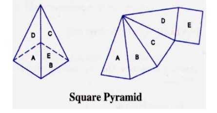
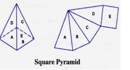
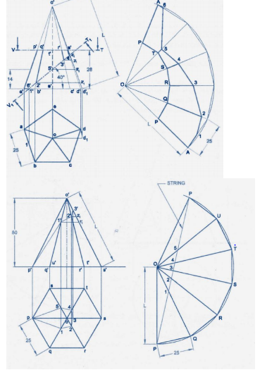
Radial Line Method:
This method of development is used for right and oblique pyramids and cones. It employs radial lines which are slant edges from vertex to base comer points for pyramids, and radial surface lines on the cone surface from the vertex to the base.
Development of Right Cones
The development of any right cone is a sector of a circle since the radial surface Lines are all of the same true length. The angle at centre of the sector depends on the base radius and the slant height of the cone. Let the radius of the base of the cone be R, the slant height of the cone be L, and the angle at the centre of the development be θ.
θ = (Radius of the base circle /True slant length) X 360 =( R / L ) X 360
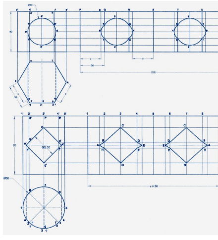
In this method of development the surface of the object is divided into a number of triangles. The true sizes of the triangles are found and then these triangles are drawn in order, side by side, to produce the pattern. It is simple to realize that to find the true sizes of the triangles, it is first necessary to find the true length of their sides.
1. When the top and bottom edges of a sheet metal detail are parallel to the HP the true lengths of these edges may be taken directly from the top view.
2. In case of circular edges, chordal distance may be taken and transferred to the development. Though such lengths are not theoretically accurate they are satisfactory for development work.
3. For all transition pieces having inclined top and bottom edges, TL construction must be carried out if these edges are curved.
4. A well-defined labelling system should be used in order that the construction technique may be progressive and easy to understand.
Comments are closed