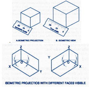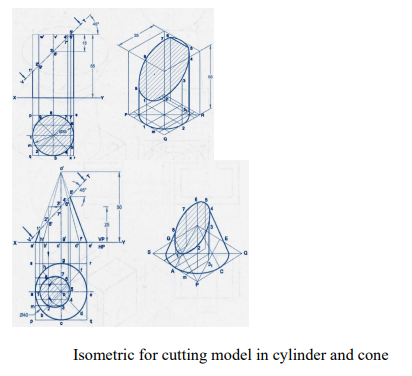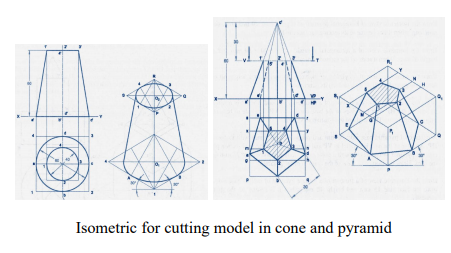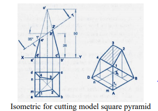
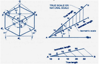
The isomeric projection of an object is obtained on a vertical plane of projection by placing the object in such a way that its three mutually perpendicular edges make equal inclinations with the plane of projection. Since the three mutually perpendicular edges of an object are projected in the isometric projection at equal axonometric angles, the angles between those edges in the isometric projection will be at 12°. The lengths of the three mutually perpendicular edges of the object in the isometric projection are foreshortened in the same proportion.
Isometric Scale:
In the isometric projection, all the edges of an object along the direction of the three isometric axes are foreshortened to 0.816 times their actual lengths. To facilitate an easy and quick method of measurement of the lengths of the different edges in their reduced sizes while drawing the isometric projection of the object, a special scale called isometric scale is constructed.
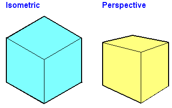
The view drawn to the actual scale is called the isometric view or Isometric Drawing while that drawn using the isometric scale is called the Isometric Projection.
Importance Points in Isometric:
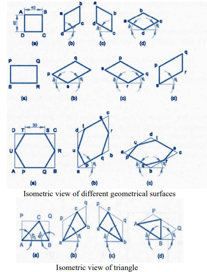
1. For drawing the isometric, the object must be viewed such that either the front -right or the left edges becomes nearest.
2. All vertical edges of the object remain vertical in isometric
3. The horizontal edges of the object which are parallel to the isometric axes are drawn at 30° to the horizontal
4. The inclined edges which are not parallel to the isometric axes should not be drawn at the given inclination in isometric. These inclined edges are drawn by first locating the end points in isometric and then joined.
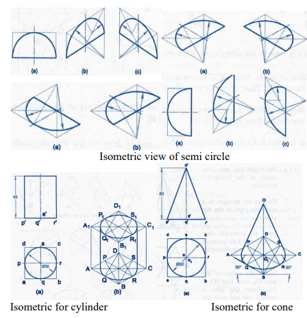
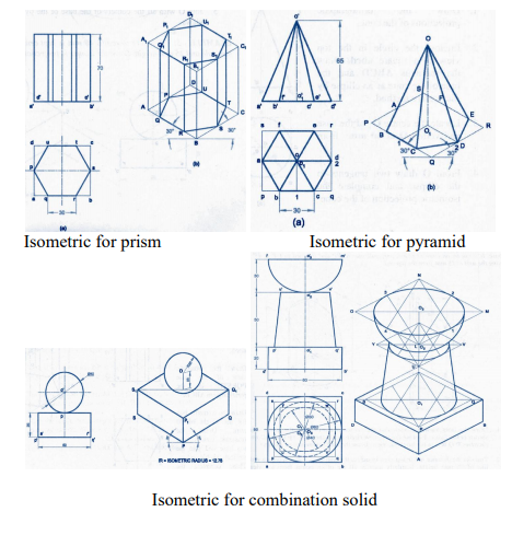
5. All circles are represented as ellipses in isometric.
6. All construction lines have to be retained as thin lines and the visible edges are to be shown as thick lines.
7. Generally the hidden edges need not be shown in isometric unless otherwise required either for locating a comer, or an edge, or face, or mentioned.
8. Unless otherwise specifically mentioned to draw the isometric view or isometric drawing all dimension lines parallel to the isometric unless otherwise if mentioned.
9. No dimensions are indicated in isometric unless otherwise mentioned.
10. The given orthographic views need not be drawn unless required for consideration