The following steps can be used to draw sectional views:
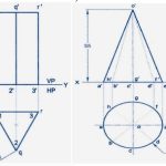
Step I: Draw the projections of the given solid in an uncut condition in both the views (the FV and the STY) by thin construction lines.
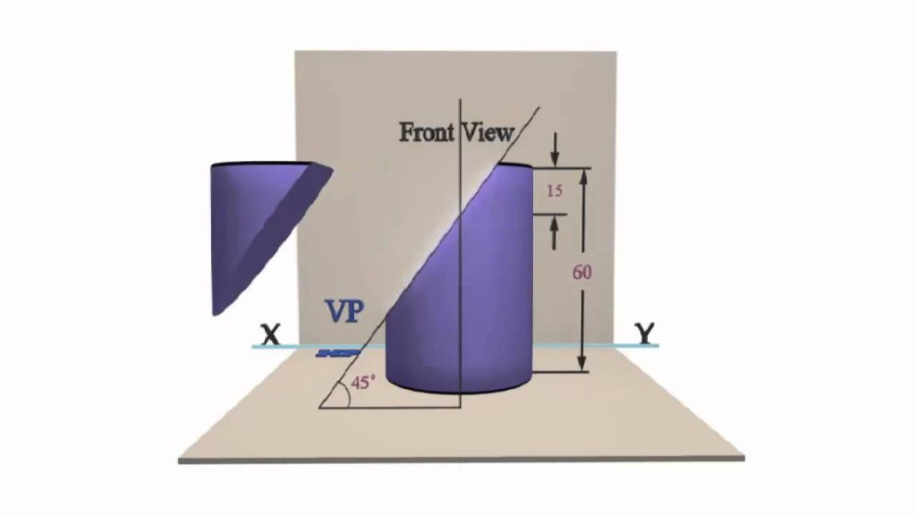
Step II: Draw the cutting plane (or the section plane) as a straight line inclined at B to the XY line in the front view if it is given to be perpendicular to the VP. Draw it inclined at B to the HP or as a straight line inclined at rp to XY in the top view, if it is given to be perpendicular to the HP and inclined at rp to the VP.
Step III: If the solid is a cylinder or a cone, draw a number of generators intersecting the cutting plane line. Obtain their projections in the other view. Generators are lines drawn through the points on the base circle and are parallel to the axis for a cylinder or joining the apex for a cone.
Step IV: Locate the point’s common between the cutting plane line and the surface lines of the solid. These surface lines include the base and side edges of prisms and pyramids or the generators and circular edges of cylinders and cones. Number these points as follows:
(i) Start from one end of the cutting plane, and move towards the other end naming the points on visible surface lines sequentially.
(ii) After reaching the other end, return along the cutting plane line and continue to number those points that are on hidden surface lines sequentially. In case of a hollow solid, imagine the hole as a separate solid and number the points in the usual manner.
Step V: Project the points in the other views by drawing interconnecting projectors and intersecting the concerned surface lines.
Step VI: Join the points obtained in Step V by continuous curved lines if the points are on a conical or a cylindrical surface. Otherwise, join them by straight lines. The apparent section is completed by drawing cross-hatching section lines within the newly cut surface.
Step VII: Complete the projections by drawing the proper conventional lines for all the existing edges and surface boundaries.
Hint To Locate The Cutting Plane:
The required cutting plane can be quickly located if the following hints are kept in mind:
1. The number of comers in the true shape of a section is always equal to the number of edges of the solid that is cut by the cutting plane.
2. The true shape of a section has a configuration similar to that of its apparent section. This means:
(i) The number of edges and corners are equal.
(ii) Any pair of lines, if parallel in one, will remain parallel in the other.
(iii) A rectangle in one need not be a rectangle in the other. Instead, it will be a four-sided figure with the opposite sides parallel. That is, it may be a rectangle, a Square or a parallelogram.
(iv) A curved boundary in one will remain a curved boundary in the other but a Circle need not be a circle. It may also be an ellipse.
3. A section as curve can be obtained only when the generators of a cylinder or of a cone are cut.
4. When a cutting plane cuts all the generators of a cylinder or a cone, then the true shape of the section is an ellipse.
5. When the cutting plane is inclined to the base of a cone at an angle that is equal to, greater than or less than that made by its generator with the base, then the true shape of the section is a parabola a hyperbola or an ellipse, respectively.
6. When a cutting plane cuts along the generators of a cone, then the true shape of the section is an isosceles triangle.
7. When a cutting plane cuts along the generators of a cylinder, then the true shape of the section is a rectangle.
The actual procedure to locate the cutting plane involves the following steps:
Step I: Draw the projections of the given uncut solid in the proper position with respect to the HP and the VP by then lines.
Step II: If the cutting plane is to be perpendicular to the VP or the HP, draw a number of trial cutting planes in the front view or in the top view, respectively. Select those cutting planes that intersect the number of edges of the solid equal to the number of corners of the true shape of the required section. If the solid is a cone or a cylinder, select the cutting plane based on Hints (4) to (7).
Step III: Sketch the shape of the section by projecting points on one of the selected cutting planes. If the cutting plane line is inclined to the XY line, the shape of the section that will be obtained will not be the true shape and it is called an apparent section.
Step IV: From a sketch of the true shape, find out the dependence of its dimensions on the various lines in projections, and find out whether by shifting the cutting plane the same edges and surfaces can be cut and whether the required lengths can be obtained for the true shape of the section. Accordingly, adjust the position of the cutting plane. If adjustment of dimensions is not possible, try another cutting plane and rework steps III and IV.