Step I: Draw the projections of the given solid in the uncut condition using thin lines.
Step II: Draw the cutting plane as a line in the front or top view depending upon whether it is perpendicular to the VP or the HP. If the cut is a cylindrical or prismatic hole, it will be drawn as a circle or a polygon in the FV or the TV depending upon whether its axis is perpendicular to the VP or the HP.
Step III: Draw a number of surface lines, particularly the ones that are intersecting the Cutting plane line and passing through the critical points as in the case of intersections of surfaces problems. For a curved solid or a curved cut, draw at least one more surface line between two adjacent critical points.
Step IV: Locate the point’s common between the cutting plane lines and surface lines, and number them in the same manner as in Chapter 10. The edges of the base or side surfaces are also surface lines.
Step V: Draw the development of the uncut solid and locate the positions of the surface Lines by thin lines drawn in Step III.
Step VI: The point’s common between the cutting plane and the surface lines named in Step IV can be located on the respective surface lines of the development at true distances from the known end points of those surface lines. If the concerned surface line does not represent the true length either in the FV or the TV, find its true length by making one view parallel to XY and transfer the cutting plane point on it. Find its true distance from one of the end points. And use this distance to plot the point in the development.
Step VII: Join the cutting plane points in serial cyclic order in the development. If the solid is a curved one or the cutting plane is curved, join the points by curved lines, otherwise, by straight lines. The number of lines in the development will be equal to the number of formed corners, and a corner may form where the edge of the solid is cut by the cutting plane or where there is a corner in the cut. If the two points to be joined in sequence are located on edges of the same base, they should be joined by moving along existing base/v edges if the development of the lateral surface is drawn.
Step VIII: Complete the development by drawing boundary lines by thick lines. Complete the projections by drawing proper conventional lines for all existing edges and surface boundaries.
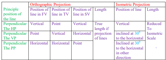
Isometric Projections:
Isometric and Orthographic Projections of Principal Lines
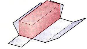
The steps for drawing isometric projections of an object are as follows:
Step I: Draw orthographic projections of the given object and enclose each view in the smallest rectangle. The sides of the rectangles should be vertical and horizontal lines only because they are supposed to be the principal lines of the enclosing box of the Object.
Step II: Select the faces that are to be visible so that the maximum number of visible Lines/surfaces are obtained in the isometric projection. Generally, the front face, the top face, and one side face are made visible. If the left-side view gives the maximum number of visible lines, the left face is made visible. If the right-side view gives the maximum number of visible lines, the right face is made visible.
Step III: Correlate the projections of the various surfaces in all the views by using the Properties of projections of plane surfaces. Having co-related the projections in two views or more, points should be measured in principal directions in any two views and should be plotted in isometric projections. Coordinate distances should be reduced to isometric scale before plotting.
Step IV: Draw all the boundaries of surfaces by proper conventional lines depending upon their visibility.
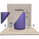
Important points in perspective projection:
i. A surface touching the PPP has its true shape and size in the perspective view.
ii. Perspective views of lines touching the PPP are of their true lengths and true inclinations.
iii. Perspective views of vertical lines are vertical lines.
iv. Perspective views of horizontal lines, parallel to each other and inclined to the PPP; converge into a single point, which is the front view of the vanishing point.
v. Perspective views of lines parallel to the PPP are parallel to the original lines.
vi. If the object is behind the PPP, the size of its perspective view will be reduced in size compared to the object. Also, the greater the distance from the PPP, the smaller the perspective.
vii. For an object of nearly equal length, width and height, the station point should be selected so that the visual rays through the outermost boundaries of the object make a 30° angle between them. If the object is small, the station point should also be selected so that a good view of the front side as well as the top of the object is obtained.