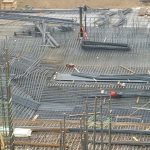
Load applied to the surface of a body distributes into the body over a successively wider area. The simplest way to calculate the stress distribution is by means of the 2(V):1(H) method. This method assumes that the load is distributed over an area that increases in width in proportion to the depth below the loaded area, as is illustrated in Fig. 1.4. Since the vertical load, Q, acts over the increasingly larger area, the stress (load per surface area) diminishes with depth. The mathematical relation is as follows.

Note, the 2:1 distribution is only valid inside (below) the footprint of the loaded area and must never be used to calculate the stress outside the footprint.
Example
The principles of calculating effective stress and stress distribution are illustrated by the calculations involved in the following soil profile: An upper 4 m thick layer of normally consolidated sandy silt is deposited on 17 m of soft, compressible, slightly overconsolidated clay, followed by 6 m of medium dense silty sand and, hereunder, a thick deposit of medium dense to very dense sandy ablation glacial till. The densities of the four soil layers and the earth fill are: 2,000 kg/m3 , 1,700 kg/m3 , 2,100 kg/m3 , 2,200 kg/m3 , and 2,000 kg/m3 , respectively. The groundwater table lies at a depth of 1.0 m. For “original conditions” (or initial condition), the pore pressure is hydrostatically distributed from the groundwater table throughout the soil profile. For “final conditions”, the pore pressure in the sand has increased to a phreatic height above ground of 5 m; the fact that the phreatic height reaches above ground makes the pressure condition “artesian”. It is still hydrostatically distributed in the sand (as is the case when a more pervious soil layer is sandwiched between less pervious soils—a key fact to consider when calculating the distribution of pore pressure and effective stress). Moreover, the pore pressure in the clay has become non-hydrostatic. Note, however, that it is linear, assuming that the “final” condition is long-term, i.e., the pore pressure has stabilized. The pore pressure in the glacial till is assumed to remain hydrostatically distributed. Finally, for those “final conditions”, a 1.5 m thick earth fill has been placed over a square area with a 36 m side.
Calculate the distribution of total and effective stresses, and pore pressure underneath the center of the earth fill before and after placing the earth fill. Distribute the earth fill, by means of the 2:1-method, that is, distribute the load from the fill area evenly over an area that increases in width and length by an amount equal to the depth below the base of fill area (Eq. 1.14).
Table 1.6 presents the results of the stress calculation for the Example 1.1 conditions. The calculation results are presented in the format of a spread sheet, a “hand calculation” format, to ease verifying the computer calculations. Notice that performing the calculations at every metre depth is normally not necessary. The table includes a comparison between the non-hydrostatic pore pressure values and the hydrostatic, as well as the effect of the earth fill, which can be seen from the difference in the values of total stress for “original” and “final” conditions.
The stress distribution below the center of the loaded area shown in Table 1.1 was calculated by means of the 2:1-method. However, the 2:1-method is rather approximate and limited in use. Compare, for example, the vertical stress below a loaded footing that is either a square or a circle with a side or diameter of B. For the same contact stress, q0 , the 2:1-method, strictly applied to the side and diameter values, indicates that the vertical distributions of stress, [qz = q0 /(B + z)2 ] are equal for the square and the circular footings. Yet, the total applied load on the square footing is 4/p = 1.27 times larger than the total load on the circular footing. Therefore, if applying the 2:1-method to circles and other non-rectangular areas, they should be modeled as a rectangle of an equal size (‘equivalent’) area. Thus, a circle is modeled as an equivalent square with a side equal to the circle radius times Öp.
Notice, the 2:1-method is inappropriate to use for determining the stress distribution below a point at any other location than well within the loaded area. For this reason, it cannot be used to combine stress from two or more loaded areas unless the footprints are similar and have the same center. To calculate the stresses induced from more than one loaded area and/or below an off-center location, more elaborate methods, such as the Boussinesq distribution, are required.


