A truss is a structure made up of slender members pin-connected at ends and is capable of taking loads at joints. They are used as roof trusses to support sloping roofs and as bridge trusses to support deck. In many machines steel trusses are used. Transmission towers are also the examples of trusses. In the case of wooden trusses, the ends are connected by making suitable joints or by nailing and bolting whereas in steel trusses ends are connected by bolting or welding. The trusses are also known as ‘pinjointed frames’.
A truss in which all the members lie in a single plane is called as a plane truss. In such trusses loads act in the plane of the truss only. Roof trusses and bridge trusses can be considered as plane trusses. If all the members of a truss do not lie in a single plane, then it is called a space truss. Tripod and transmission towers are the examples of space trusses. In this chapter, the analysis of only plane trusses is considered.
Perfect, Deficient And Redundant Trusses
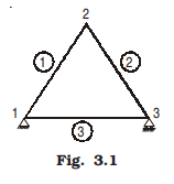
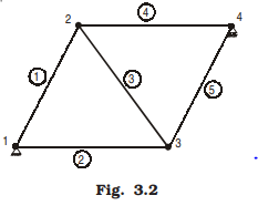
A pinjointed truss which has got just sufficient number of members to resist the loads without undergoing appreciable deformation in shape is called a perfect truss. Triangular truss is the simplest perfect truss and it has three joints and three members (Fig. 3.1). Perfect trusses with four and five joints are shown in Figs. 3.2 and 3.3 respectively.
It may be observed that to increase one joint in a perfect truss, two more members are required. Hence the following expression may be written down as the relationship between number of joints j, and the number of members m, in a perfect truss.
m = 2j – 3 …(3.1)
However, the above equation gives only a necessary, but not a sufficient condition of a perfect truss. For example, the two trusses shown in Fig. 3.4(a) and (b) have the same number of members and joints. The truss shown in Fig. 3.4(a) is perfect whereas the one shown in Fig. 3.4(b) is not capable of retaining its shape if loaded at the joint marked 6. Therefore, the only necessary and sufficient condition of a perfect truss is that it should retain its shape when load is applied at any joint in any direction.
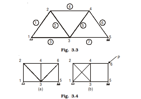
A truss is said to be deficient if the number of members in it are less than that required for a perfect truss. Such trusses cannot retain their shape when loaded. A deficient truss is shown in Fig. 3.5.
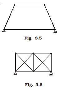
A truss is said to be redundant if the number of members in it are more than that required in a perfect truss. Such trusses cannot be analysed by making use of the equations of equilibrium alone. Thus, a redundant truss is statically indeterminate. Each extra member adds one degree of indeterminancy. For the analysis of such members the consistency of deformations is to be considered. The truss shown in the Fig. 3.6 is a typical redundant truss. In this truss one diagonal member in each panel is extra. Hence it is a two-degree redundant truss. In this chapter, only the analysis of perfect frames is considered.
ASSUMPTIONS
In the theory that is going to be developed in this chapter, the following assumptions are made:
(1) The ends of the members are pin-connected (hinged);
(2) The loads act only at the joints;
(3) Self-weights of the members are negligible;
(4) Cross-section of the members is uniform.
If at all the cross-section varies, the centre of gravity of the section is assumed to be located along the same longitudinal line.
In reality the members are connected by bolting, riveting or by welding. No special care is taken to ensure perfect pin-connections. However, experiments have shown that assuming pin-connected ends is quite satisfactory since the members used are slender.
In most of the frames the loads act at the joints. Even if a load is not acting at a joint, it can be replaced by its reaction at the joint and a local bending effect on the member. The frame may be analysed for the joint loads and the local bending effect on the member superposed in the design of that member.
In most of the trusses, the self-weight is really small compared to the loads they carry. Hence self-weight of the members may be neglected.
It is the duty of construction engineer to see that the centroid of all cross-sections lie along a single axis so that the member is held in equilibrium by the two forces acting at its ends.