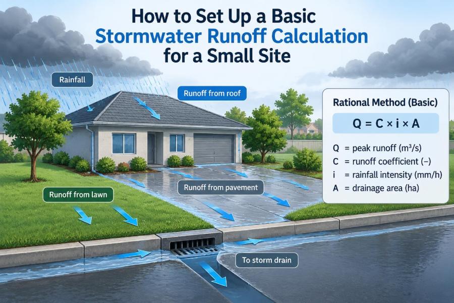

A small car park, a house extension, a compact warehouse yard, or a redeveloped corner lot can change drainage behaviour far more than it first appears. A few new roofs and paved areas may send rainfall to one low point much faster than the original grass or soil ever did.
That matters when sizing a roadside connection, a swale, a pipe, a small detention feature, or a site inlet. If the estimated runoff is too low, water may pond, bypass an inlet, erode a slope, or affect a neighbouring property. If it is too high, a simple project can become unnecessarily expensive.
For many preliminary designs, the Rational Method provides a practical starting point. It converts a chosen design rainfall intensity, site area, and runoff coefficient into an estimated peak flow rate.
The method is deliberately simple, but good results still depend on disciplined inputs, sensible assumptions, and awareness of its limits. Here is a clear workflow for setting up a basic stormwater runoff calculation for a small site.
🧭 Start with the question the calculation must answer
Before selecting a formula, define the drainage decision. Are you estimating flow to size a short pipe, checking the capacity of an existing ditch, or determining whether a small site needs temporary storage?
A runoff calculation produces a design peak discharge: the estimated highest rate of flow expected during a selected storm. It does not, by itself, tell you the total storage volume needed over an entire storm, the quality of runoff, or whether a downstream network is adequate.
Writing the purpose at the top of the calculation sheet prevents a common error: using one number to answer several different hydraulic questions.
🏗️ Confirm that the site is suitable for a basic method
The Rational Method is generally most useful for relatively small drainage catchments with a reasonably direct flow path. It is often used for preliminary work and for small developed areas, subject to the requirements of the relevant authority or client standard.
It becomes less dependable when a catchment is large, has several distinct travel paths, includes extensive storage, or has complicated natural channels. In those cases, a hydrograph-based model may better represent how flow changes over time.
Do not assume that “small” automatically means simple. A small site with a steep rear slope, multiple inlet points, or off-site runoff crossing its boundary can need more careful assessment than a larger, self-contained paved yard.
🗺️ Define the drainage catchment boundary
A catchment is the area that drains to the point being checked, called the point of interest or outlet. Mark that outlet first, then trace the high ground, kerbs, walls, channels, and roof drainage routes that direct water toward it.
Drainage boundaries do not always match property boundaries. A retaining wall may block flow; a driveway crossover may direct it; and an adjoining slope may contribute water from outside the property.
For a roof, follow gutters and downpipes rather than assuming water flows in the direction of the roof slope alone. For paved areas, inspect kerb grades, pavement falls, and inlet locations.
📐 Measure contributing area carefully
Calculate the plan area of every surface that contributes to the outlet. Use scaled survey information, a drainage plan, or a reliable site measurement method. Keep a clear sketch showing each subarea and its drainage direction.
Use one area unit consistently. Hectares are common in SI Rational Method equations, while square metres are often more intuitive for small sites. Conversion mistakes are easy to make: 1 hectare equals 10,000 square metres.
Exclude areas that genuinely drain elsewhere. Conversely, include driveways, strips between buildings, and hardstanding that may look minor but route water toward the same low point.
🧩 Split mixed surfaces into subcatchments
A site rarely has one uniform surface. Break it into zones with meaningfully different runoff behaviour, such as roof, asphalt, concrete, gravel, lawn, and landscaped soil.
This approach is more transparent than assigning one rough coefficient to the entire site. It also makes future review easier: another engineer can see why the calculated runoff increased after a proposed parking area replaced planting.
Subcatchments may also be divided by route. Two asphalt areas can require separate treatment if one drains to a rear soakaway and the other drains to the public stormwater system.
💧 Understand what runoff coefficients represent
The runoff coefficient, usually written as C, represents the portion of rainfall assumed to become direct runoff at the outlet. It is dimensionless, so it has no unit.
A higher coefficient indicates less infiltration, depression storage, and surface retention. Smooth roofs and sealed pavement generally have high values. Lawns and permeable soil generally have lower values, but their actual response depends strongly on compaction, slope, soil condition, and antecedent wetness.
C is a planning parameter, not a permanent physical constant. A lawn during a dry period may respond very differently from the same lawn after prolonged rainfall.
🧱 Select coefficients from an approved source
Use runoff coefficients required or recommended by the governing drainage manual, municipality, road authority, or project specification. Local guidance may prescribe values by land use, surface type, return period, or regional condition.
Avoid copying a coefficient from an unrelated online example. Published ranges can be useful for a reasonableness check, but they do not override local criteria.
| Surface type | Typical runoff tendency | Design consideration |
|---|---|---|
| Metal or tiled roof | High | Confirm gutter and downpipe routing. |
| Concrete or asphalt | High | Account for kerbs and low points that concentrate flow. |
| Compacted gravel | Moderate to high | Do not treat it automatically as fully pervious. |
| Landscaped soil or lawn | Variable | Consider slope, compaction, and drainage condition. |
The table describes behaviour, not mandatory coefficient values. The approved design reference should provide the actual values used.
⚖️ Calculate a weighted runoff coefficient
Where several surfaces drain to one outlet, calculate an area-weighted coefficient rather than averaging coefficients directly. The equation is Cw = Σ(Ci × Ai) / ΣAi, where each surface has coefficient Ci and area Ai.
Suppose, hypothetically, that a 1,000 m² site has 600 m² of roof and pavement assigned C = 0.90, plus 400 m² of landscaped area assigned C = 0.30. The weighted coefficient is ((0.90 × 600) + (0.30 × 400)) / 1,000 = 0.66.
That result reflects both surface response and surface extent. The smaller landscaped portion reduces runoff, but it cannot make the whole site behave like open ground.
🌦️ Choose the design storm return period
A return period is a way of expressing the rarity of a rainfall event used for design. The required event depends on what is being designed and what consequence is acceptable if capacity is exceeded.
For example, a minor internal drainage component may be checked against a less severe event than a major overland flow path that must protect buildings. Local drainage policies often state the required return periods and any climate-related allowances.
A return period is not a timetable. A storm described by a particular annual exceedance probability can occur more than once in a short period, or not occur for many years.
📊 Obtain local rainfall intensity data
The Rational Method needs rainfall intensity, commonly expressed in millimetres per hour. Obtain it from the approved local intensity-duration-frequency data source, often abbreviated as IDF data.
Intensity varies with storm duration and chosen return period. Short, intense storms may control inlet and pipe design on a compact site, while longer events may be more relevant to detention storage.
Record the data source, station or regional basis, return period, duration, and any adjustment factor. Rainfall inputs are too consequential to leave as an unexplained number in a spreadsheet cell.
⏱️ Estimate the time of concentration
The time of concentration, usually written as Tc, is the estimated time for runoff to travel from the hydraulically most remote point of the catchment to the outlet. In Rational Method practice, the storm duration used to select rainfall intensity is commonly set equal to Tc.
For a compact site, Tc may include sheet flow over a roof or pavement, shallow concentrated flow along a swale or kerb, and pipe travel time. The longest physical route is not always the controlling route; travel speed matters too.
Use a method accepted by the relevant design standard. Short assumed times can produce high intensities, so they should be justified rather than chosen simply because they appear conservative.
🛤️ Trace the longest hydraulic path
Draw the route water actually follows from the remote point to the outlet. Break it into segments where flow type changes: sheet flow, shallow concentrated flow, gutter flow, channel flow, or pipe flow.
For each segment, note length, slope, surface condition, and likely flow depth where relevant. A roof may drain quickly to a gutter, while a nearly flat landscaped strip may delay runoff before it reaches a grate.
This tracing exercise often reveals design issues before any equation is used, including a local sag point, an unprotected slope, or a flow path that crosses a pedestrian route.
🧮 Use a consistent form of the Rational Method
The basic relationship is Q = C i A, but the units must be compatible. In a common SI form, Q (m³/s) = 0.00278 × C × i (mm/h) × A (ha).
For a small-site calculation using square metres, an equivalent convenient form is Q (L/s) = C × i (mm/h) × A (m²) / 3600. The factor converts rainfall depth over area into litres per second.
Use the formula specified by your local standard where one is given. Do not combine a factor from one unit system with area or intensity values from another.
🔢 Work through a simple hypothetical example
Consider a hypothetical 1,000 m² catchment draining to one inlet. From the earlier surface breakdown, take the weighted runoff coefficient as 0.66. Assume approved local data gives an intensity of 75 mm/h for the selected return period and Tc.
Using Q = C × i × A / 3600, the estimated peak flow is 0.66 × 75 × 1,000 / 3600 = 13.75 L/s, rounded appropriately as 13.8 L/s.
This is not a universal design value. It is an illustration of the calculation sequence. A real design must use site-specific area, coefficient, duration, rainfall data, and governing criteria.
📝 Keep a transparent calculation schedule
A calculation should be easy to audit. Include a small schedule listing each subcatchment, surface description, area, coefficient, product of area and coefficient, drainage destination, and any notes.
Then show the weighted coefficient, Tc method, rainfall intensity source, selected formula, unit conversions, and final flow. A sketch alongside the schedule is often more valuable than a polished equation alone.
Transparency is particularly helpful when plans change. If 80 m² of landscaping becomes paving, the designer can update one row and immediately see the effect on the result.
🔍 Check units before trusting the answer
Dimensional checking catches many stormwater errors. In the square-metre form, millimetres per hour multiplied by square metres represents a volume rate after the appropriate conversion; the final answer should be in litres per second.
Perform a quick order-of-magnitude check. A one-hectare area receiving 1 mm of rain contains 10 m³ of water. That physical relationship can help identify a result that is implausibly small or large.
Also check whether the reported unit is clearly stated. A number labelled only “Q = 14” is incomplete and can be dangerously misunderstood.
🏠 Account for roof drainage explicitly
Roofs usually respond quickly because they have little storage and commonly drain through gutters and downpipes. Map each downpipe destination: a piped system, rain garden, tank overflow, splash block, or surface discharge route.
If roof water is retained in a tank, do not assume the tank always reduces the design peak. Its effectiveness depends on available storage before the storm, outlet arrangement, overflow level, and any required bypass for intense rainfall.
For preliminary peak-flow work, treat a roof as contributing unless the storage and controlled outlet are explicitly modelled under the applicable design approach.
🌱 Treat pervious areas with realistic caution
Soil and landscaping can reduce direct runoff, but not without limits. Construction traffic can compact a future lawn; clayey soil may infiltrate slowly; and saturated ground may shed water like a much harder surface.
Small landscaped strips behind kerbs can also become disconnected from the wider soil profile. Water may pond briefly, then overflow to pavement or a grate rather than infiltrate at the rate assumed in a concept sketch.
Where infiltration is intended as a drainage measure, it generally requires separate investigation of soil conditions, groundwater, setbacks, maintenance, and safe overflow routing.
🕳️ Separate peak flow from storage volume
A pipe or inlet capacity check focuses on flow rate. A detention basin, tank, or underground storage system needs a volume assessment: how much water enters over time versus how much leaves.
The Rational Method can support simplified storage estimation in some procedures, but a single peak flow does not automatically provide a storage volume. A hydrograph or an approved routing method may be required.
This distinction avoids an expensive misconception: a system can pass the peak flow at one location yet still require storage because the downstream allowable discharge is lower.
🧵 Check the route after calculating flow
A calculated flow must travel through something. Review each element in sequence: surface grading, grate or inlet, pipe, pit, swale, outlet, and receiving system.
The capacity of the smallest or least efficient element controls the system. A large pipe does not solve a drainage problem if water cannot enter the grate without bypassing across a driveway.
Also identify the major overland flow path for storms that exceed the minor system. It should direct excess water away from buildings, doors, electrical equipment, and vulnerable neighbouring land where practicable.
📉 Consider slope, velocity, and erosion
Flow rate alone does not describe erosion risk. Steep pavement, swales, and outlet slopes can create high velocities even on small sites, particularly where runoff is concentrated by a pipe or kerb.
Check whether an outlet needs energy dissipation, such as a properly detailed rock protection system, a level spreader where suitable, or another erosion-control measure. The selected measure must match the expected flow, slope, soil, and maintenance conditions.
Slow water is not always harmless either. Very flat areas can pond, trap sediment, and create nuisance conditions if levels and maintenance are poor.
🚧 Include upstream and off-site runoff
A site calculation limited to new impervious area may miss water arriving from an uphill lot, roadway, or natural slope. During a storm, that external contribution can be more influential than a small new roof.
Identify existing culverts, kerb openings, fence gaps, and drainage easements. Confirm whether an apparent ditch is an active flow route or merely a shallow landscape feature.
Responsibility for managing off-site flow can involve planning, legal, and property issues. The hydraulic fact remains simple: if water can reach the site outlet, it may need to be considered in the design check.
⚠️ Avoid common calculation mistakes
- Averaging coefficients without area weighting: a small lawn should not offset a large roof by equal arithmetic influence.
- Using total property area: only the area draining to the point of interest belongs in that catchment.
- Mixing units: hectares, square metres, cubic metres per second, and litres per second require the correct formula factor.
- Choosing rainfall duration arbitrarily: intensity should align with the adopted time of concentration and governing method.
- Ignoring bypass flow: inlet capture and surface routing can govern performance before the pipe does.
- Hiding assumptions: unexplained inputs make review and revision unreliable.
🧪 Perform sensitivity checks on uncertain inputs
Early-stage site information is often incomplete. Rather than presenting one result as exact, test how the peak flow changes if a key assumption changes within a reasonable, documented range.
For example, compare the proposed paved layout with a future fully paved option, or review a somewhat longer and shorter Tc where the path is uncertain. This shows which input most influences the outcome.
Sensitivity checks do not replace proper data. They help target effort: if a small change in rainfall intensity substantially changes pipe selection, obtaining the correct local data becomes a priority.
📋 Respect authority requirements and project standards
Drainage design criteria are location-specific. Authorities may specify rainfall sources, minimum Tc values, runoff coefficients, allowable discharge rates, pipe grades, freeboard, water-quality treatment, and climate allowances.
Project requirements can be more stringent where a site connects to a constrained network or drains toward a sensitive waterway. Follow the controlling standard rather than relying solely on a classroom example.
Where requirements conflict or are unclear, record the issue and obtain direction from the responsible engineer or approving body. Assumptions should be agreed before detailed design is locked in.
🦺 Know when professional review is necessary
A basic calculation is an excellent learning tool and a useful preliminary check. It is not a substitute for professional design where public infrastructure, building protection, flood risk, steep terrain, retaining structures, contaminated land, or regulatory approval is involved.
Professional review is especially warranted when discharge leaves the site, flows toward another property, depends on infiltration, or must meet a formal consent condition. Site surveying and hydraulic assessment may reveal constraints that a desktop calculation cannot see.
Good engineering includes recognising the boundary between a useful estimate and a design that needs further analysis.
✅ Use a repeatable small-site workflow
- Identify the outlet and draw the catchment boundary.
- Measure contributing surfaces and split them into logical subcatchments.
- Select approved runoff coefficients and calculate a weighted value.
- Trace the hydraulic path and estimate Tc using the required method.
- Obtain rainfall intensity for the selected duration and return period.
- Apply a unit-consistent Rational Method equation.
- Check the result against inlets, pipes, overland routes, and outlet conditions.
- Document assumptions, sources, calculations, and limitations.
This sequence is straightforward enough to repeat, yet detailed enough to expose the decisions that control the final answer.
🎯 The core principle: trace water before calculating it
The most reliable small-site runoff calculation begins with observation, not arithmetic. Understand where water lands, which surfaces shed it, how it travels, where it concentrates, and where it can safely go when the system is overwhelmed.
The Rational Method then provides a disciplined estimate of peak flow using three central inputs: catchment area, runoff response, and design rainfall intensity. Its simplicity is useful precisely because every assumption remains visible.
A defensible stormwater estimate is not just a formula result; it is a clear, unit-consistent description of how a particular site sheds rain.
Map the flow path, use locally appropriate design inputs, and treat the calculated peak as one part of a complete drainage check. That approach makes even a basic stormwater calculation more practical, reviewable, and safer to apply. 🌧️📐💧