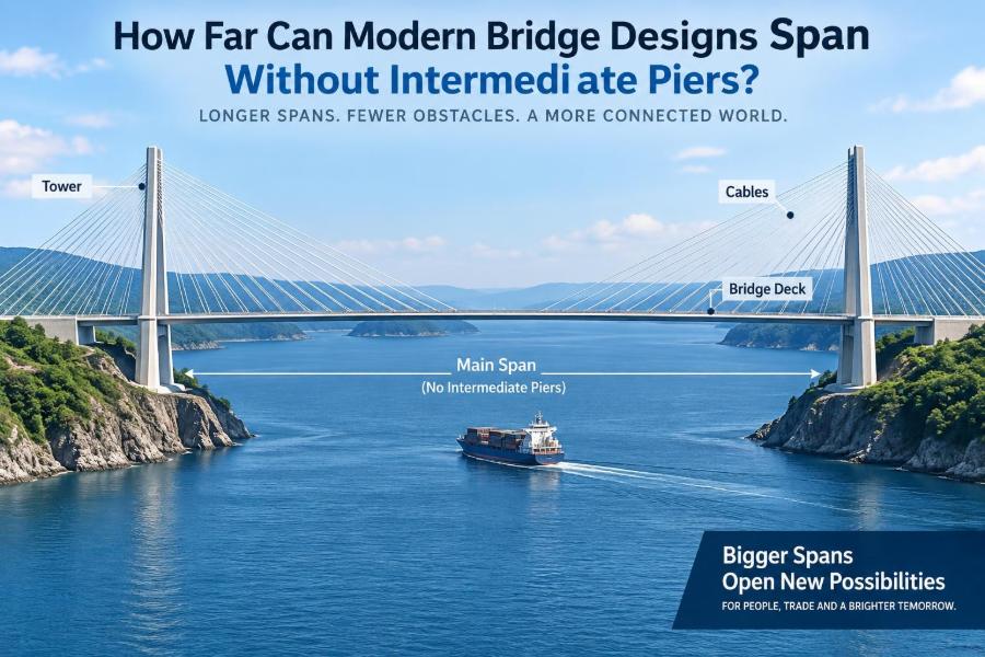

A wide estuary, a deep shipping channel, a mountain gorge, or a busy urban rail corridor can turn a seemingly simple crossing into a difficult question: where can the supports go?
Intermediate piers are often the most economical way to carry a bridge. But sometimes they obstruct ships, sit on poor ground, disrupt a protected riverbed, or create an unacceptable hazard in the path of traffic below. In those situations, engineers must make the deck reach farther.
Modern bridges can cross extraordinary distances without supports in the middle, yet there is no single maximum span. The practical answer depends on the structural system, material, wind climate, foundations, construction method, and the bridge’s intended use.
Understanding those trade-offs helps students see why a bridge is never just a line across a gap. It is a carefully balanced structural response to a specific place.
🧭 What “Without Intermediate Piers” Actually Means
A clear span is the unsupported distance between two supports. For a bridge over a channel, that usually means the distance between the main piers or abutments at each side of the navigable opening.
“Without intermediate piers” does not mean a bridge has no supports at all. Every bridge must transfer load into the ground somewhere. The question is whether supports can be placed within the obstacle being crossed.
For a suspension bridge, the central span may be held by towers at its ends, with anchorage structures farther back. For an arch, the supports are at the springing points on each side. The load path differs, but the clear-span challenge remains the same.
📏 Why Span Length Is Not One Universal Number
A bridge designed for pedestrians can be much lighter than one carrying freight trains. A crossing in a sheltered valley faces different demands from one exposed to strong coastal winds or earthquake shaking.
The limiting condition may also be something other than strength. A deck might be strong enough on paper but deflect too much under traffic, vibrate uncomfortably, or become difficult to inspect and maintain.
Therefore, engineers do not ask only, “Can this bridge reach that far?” They ask whether it can do so safely, economically, durably, and with acceptable behaviour over its design life.
🏗️ The Main Bridge Forms at a Glance
Different structural forms are efficient at different span ranges because they direct forces in different ways. A beam mainly resists bending; an arch largely develops compression; a cable-supported bridge converts much of the deck load into cable tension.
| Bridge form | Primary structural action | Typical role in long crossings |
|---|---|---|
| Beam or girder | Bending and shear | Short to medium spans, often with repeated piers |
| Truss | Axial tension and compression in members | Medium to long spans where depth is acceptable |
| Arch | Compression with horizontal thrust | Deep valleys and strong side foundations |
| Cable-stayed | Deck supported directly by inclined stays | Long spans with relatively stiff decks |
| Suspension | Deck hung from main cables | The longest practical clear spans |
These categories overlap. Hybrid designs often combine them, especially where approach spans and the main crossing have different requirements.
🪵 Beam Bridges and the Rapid Growth of Bending
A simple beam bridge is intuitive: place a plank across two supports and load it in the middle. The plank bends, with compression near its top and tension near its bottom.
As the span grows, bending moments and deflections rise rapidly. A deeper girder can help, but additional depth adds weight, and that weight creates more load for the structure to carry.
Continuous girders, box girders, prestressed concrete, and steel plate girders extend the practical range well beyond a simple beam. Even so, pure girder solutions become increasingly material-intensive when a major unobstructed gap must be crossed.
🔺 Trusses: Depth Used Efficiently
A truss uses a pattern of interconnected members, ideally carrying load primarily through tension or compression rather than large bending moments. This can provide high stiffness with less material than a solid deep web.
Historically, steel trusses enabled major railway and highway crossings. They remain useful where a deep structural profile is acceptable and where the arrangement of members does not interfere with clearance requirements.
The trade-off is complexity. A truss can contain many connections, fatigue-sensitive details, and surfaces that need inspection and corrosion protection. For extremely long modern spans, cable systems are generally more competitive.
🏛️ Arch Bridges and the Need for Strong Ground
An arch is naturally suited to compression. Under vertical loading, it pushes downward and outward at its supports, called springings. This horizontal force, or thrust, must be resisted by foundations, rock, or substantial adjacent structure.
That is why arches are especially attractive across gorges with strong rock at both sides. The valley itself can provide the geometry and foundation conditions that the bridge needs.
An arch can create a large open space below the deck, but it is not automatically the answer to every long crossing. Soft soils, weak abutment ground, or difficult access at the sides may make its thrust costly to manage.
🧵 Suspension Bridges Reach the Greatest Distances
For the longest clear spans, suspension bridges are the established solution. Their main cables curve between tall towers, and vertical suspenders hang the deck from those cables.
Steel is exceptionally effective in tension, allowing the main cables to carry enormous forces with comparatively little material. The towers transfer cable forces downward, while anchorages resist the large horizontal pull at each end.
Major suspension bridges have demonstrated central spans exceeding two kilometres. That achievement does not mean every site should use one: their towers, anchorages, aerodynamic deck design, and construction operations are substantial undertakings.
🎻 Cable-Stayed Bridges Occupy a Valuable Middle Ground
In a cable-stayed bridge, inclined cables connect the deck directly to towers. Unlike a suspension bridge, there is usually no separate freely draped main cable supporting vertical hangers across the main span.
This arrangement produces a stiffer system, which can be helpful for road and rail traffic. It also avoids the massive end anchorages associated with suspension bridges because the cable forces are balanced largely through the towers and deck.
Cable-stayed bridges are often an effective choice for long water crossings where a large central opening is needed but a suspension bridge would be disproportionate. Their feasible span depends strongly on deck stiffness, tower form, cable arrangement, and construction staging.
⚖️ Strength Is Only One Part of Structural Performance
A bridge must not collapse, but it also must remain functional in everyday service. Engineers check stresses and capacities at severe load combinations, then separately assess deflection, vibration, cracking, ride quality, and user comfort.
A very flexible deck may be safe yet unpleasant for drivers, difficult for railway operations, or vulnerable to repeated movement at joints and bearings. Long spans make these serviceability checks particularly influential.
The best long-span structure is therefore not necessarily the lightest possible structure. It is one with enough strength, stiffness, redundancy, and durability for its location and purpose.
🌬️ Wind Can Control the Entire Design
Wind is one of the defining challenges of long-span bridge engineering. As span increases, decks tend to become more flexible, while large exposed surfaces invite aerodynamic forces.
Wind does not act only as a steady sideways push. It can generate turbulence, twisting, vertical motion, and self-excited vibration. Aeroelastic behaviour describes the interaction in which wind-induced motion changes airflow and can amplify the motion further.
Engineers investigate this using wind-climate data, physical model testing where warranted, and detailed analysis. Deck shape, edge fairings, barriers, cable spacing, and structural damping can all affect performance.
🎼 Vibration Matters Even When Wind Is Modest
Pedestrians can feel rhythmic movement on a slender footbridge. Road vehicles can excite local deck vibrations, and trains impose repeated moving loads that demand particularly careful dynamic assessment.
Long cables may also vibrate in wind and rain. If not controlled, cable motion can create fatigue concerns at anchorages and reduce durability. Dampers, cross-ties, aerodynamic detailing, and adjusted cable properties are among the measures used.
These issues illustrate a key lesson: long-span design is a dynamic problem, not simply a calculation of static weight.
🚢 Navigation Clearance Often Removes the Pier Option
Shipping routes may require a wide, unobstructed channel and sufficient vertical clearance below the deck. A pier in the wrong position can restrict vessel movement and introduce a serious collision hazard.
A navigation authority may define a preferred channel alignment, but engineers still need to consider future vessel operations, water depth, currents, and emergency manoeuvring. The clear span must work with the whole waterway, not just a line on a drawing.
Removing a central pier can reduce one risk while increasing span cost. The final arrangement compares these competing consequences rather than assuming that fewer piers are always better.
🌊 Rivers Add Scour, Flood, and Debris Hazards
Bridge piers in flowing water alter the current. Flow accelerates around the foundation, potentially removing bed material in a process called scour. Floods can deepen scour and carry debris that catches on piers.
In some rivers, avoiding in-channel foundations reduces environmental disruption and hydraulic uncertainty. It can also preserve flood conveyance by leaving the channel more open.
However, a longer main span may require taller side piers or wider foundations near the banks. Hydraulic and geotechnical design must consider the entire crossing, including how floodwaters move across floodplains and approaches.
🪨 Foundation Capacity Sets a Quiet but Firm Limit
Elegant superstructure concepts can fail economically if the ground cannot support their reactions. Suspension towers and cable-stayed pylons concentrate very large vertical and horizontal forces at a few locations.
Rock foundations may offer excellent support, while deep soft deposits can require piles, drilled shafts, ground improvement, or extensive foundation caps. Those solutions are feasible, but they influence cost, programme, and construction risk.
For an arch, the ability of the banks to resist horizontal thrust is fundamental. For a suspension bridge, the anchorage ground must reliably resist the cable pull. The ground is part of the structure.
🧱 Material Choice Changes the Span Equation
Steel has high tensile strength and relatively low self-weight, which makes it central to cables, long trusses, and slender deck systems. Its main challenges include corrosion protection, fatigue detailing, and the need for reliable fabrication and erection quality.
Concrete is strong in compression, durable when properly designed and built, and widely available. Prestressing introduces intentional compression so concrete can better resist tensile effects from service loads.
Composite construction uses steel and concrete together, often allowing each material to contribute where it performs best. The right choice depends on supply chains, climate, maintenance resources, construction access, and structural form—not strength alone.
📉 Self-Weight Becomes the Long-Span Tax
Every bridge carries its own weight before it carries a single vehicle. As spans grow, self-weight can become the dominant permanent load, especially in deep or heavily stiffened decks.
This creates a difficult cycle: a heavier deck needs larger cables, towers, girders, and foundations; those elements add more weight; and the entire system grows again. Efficient long-span design is largely an exercise in managing this cycle.
Lightweight decks can be advantageous, but they must still provide stiffness, durability, fire resistance where relevant, and protection against wind-induced movement. Reducing mass without understanding the dynamic consequences can create new problems.
🛣️ The Bridge’s Use Determines Its Tolerance for Movement
A pedestrian bridge can accept more visible movement than a high-speed railway bridge, although comfort remains important. Road bridges lie between these extremes: they need predictable vehicle handling, controlled deck movements, and maintainable expansion details.
Railway bridges often demand particularly high stiffness because track geometry and repeated axle loads are sensitive to deflection and vibration. A design acceptable for highway traffic may be unsuitable for rail without substantial changes.
Utility bridges, pipelines, and light transit structures bring their own loading and access needs. The maximum feasible span is always tied to the service the bridge must provide.
📐 Deck Depth Is a Design Constraint, Not Just an Aesthetic Choice
A deep deck can be structurally efficient because it increases the distance between compression and tension zones, raising bending resistance and stiffness. But depth may reduce navigation clearance or conflict with required approach-road grades.
A shallow deck preserves clearance and can look elegant, yet it often needs more advanced structural detailing, higher-strength materials, or stronger cable support. There is no free reduction in depth.
Architectural goals matter, especially for landmark crossings, but the deck profile must still satisfy structural mechanics, drainage, inspection access, and construction tolerances.
🏗️ Construction Method Can Decide What Is Feasible
Some bridges are assembled from temporary falsework below the deck. That is practical over dry ground or shallow, accessible water, but impossible or unacceptable over deep channels, active railways, or sensitive habitats.
Long-span bridges often use cantilever erection, launching, cable-supported segmental construction, lifting from barges, or prefabricated units installed during short closures. Each method changes the forces the unfinished bridge experiences.
Construction-stage analysis is essential. A bridge may be safe in its completed form yet vulnerable while only part of the deck or cable system is in place.
🧩 Temporary Conditions Are Real Structural Conditions
During construction, a partially completed bridge can be more flexible than the final structure. Loads from cranes, wind, equipment, wet concrete, and uneven segment placement may govern particular members or connections.
Cable-stayed bridges require carefully controlled sequence and cable tensioning. Small deviations can alter deck geometry and redistribute forces. Suspension bridge cable spinning and deck installation likewise demand rigorous survey control.
Temporary works deserve the same engineering discipline as permanent works. They are not merely site logistics; they are part of the load path until the permanent system is complete.
🔍 Fatigue and Detail Design Grow More Important Over Time
Bridges experience millions of traffic cycles over decades. Even stresses below a material’s immediate strength can gradually damage susceptible details, especially welded steel connections, cable anchorages, and attachments exposed to vibration.
Good fatigue design avoids abrupt changes in geometry, controls welding quality, and provides inspectable details. It also considers drainage, because water trapped at connections can accelerate corrosion and hide deterioration.
For a major clear span, replacement of a critical cable or joint may be difficult and disruptive. Designing for inspection and future intervention is a practical form of resilience.
🧰 Bearings, Expansion Joints, and Movements at the Ends
Long bridges expand and contract with temperature. They also move under traffic, wind, creep and shrinkage in concrete, and long-term cable adjustments. Those movements must go somewhere.
Bearings guide or permit movement while transferring vertical and lateral reactions. Expansion joints accommodate deck movement at selected locations, but they are exposed components that can require frequent maintenance.
A longer span does not simply challenge the centre of the bridge. It increases demands at the interfaces where deck, pier, abutment, roadway, and drainage systems meet.
🌍 Earthquakes Change the Preferred Structural Strategy
In seismic regions, long-span bridges must accommodate ground movement, inertia forces, and potential differences in motion between foundations. Tall towers and flexible decks require a whole-system response assessment.
Isolation bearings, dampers, ductile detailing, restrainers, and foundation design can improve performance, but the appropriate measures depend on the seismic hazard and local ground conditions. A solution effective at one site may be unsuitable at another.
Engineers must also examine whether a fault crossing, liquefiable soil, slope instability, or tsunami exposure affects the route. Span selection cannot be separated from hazard-informed site planning.
🌱 Environmental Benefits and Trade-Offs of Fewer Piers
Eliminating piers from a river or wetland can reduce direct disturbance to habitat, avoid in-water construction, and preserve water flow patterns. It may also reduce the area exposed to vessel collision or floating debris.
Yet a longer bridge can need larger approach structures, taller towers, more material, and more construction access from the banks. Visual effects, bird interactions, noise, and carbon associated with materials still need assessment.
The environmentally preferable option is site-specific. Fewer supports in the water can be beneficial, but it should be evaluated alongside the wider footprint of the complete project.
💰 Why the Longest Possible Span Is Rarely the Cheapest
Increasing clear span can eliminate costly marine foundations, but it usually raises superstructure cost, fabrication demands, erection complexity, and wind-engineering requirements. The cost curve is not linear.
A shorter bridge with several well-positioned piers may be more economical where foundations are straightforward and navigation is limited. Conversely, one large span can be justified where each in-water pier would be exceptionally difficult, hazardous, or disruptive.
Early option studies compare lifecycle cost rather than only initial construction cost. Painting access, cable inspection, joint replacement, corrosion exposure, and future closures can affect the long-term decision.
🗺️ Site Geometry Often Matters More Than a Record Span
A crossing might need a 300-metre opening because that is the width of a shipping channel, not because a designer is trying to maximize span. The landform, road alignment, and clearance envelope establish the real engineering problem.
For example, a hypothetical bridge across a narrow but deep gorge may favour an arch or cable-stayed configuration because strong rock is available on both sides. A broad estuary with weak soils and major navigation could point toward a suspension bridge with towers located outside the channel.
The most appropriate span is the one that fits the site with the fewest unacceptable compromises.
🏆 Record Bridges Show Capability, Not a Standard Template
Record-setting bridges demonstrate what materials, analysis, construction control, and aerodynamic design can achieve. They are valuable case studies, particularly for how engineers handle wind, cable forces, foundation conditions, and staged erection.
But a record bridge is usually a response to unusual geographic and transport constraints. Its scale may require specialized fabrication, major temporary works, highly developed inspection systems, and a level of investment unavailable to ordinary projects.
Students should treat famous bridges as evidence of possibilities, not as a catalogue of forms to copy. The transferable lesson is the design process behind them.
🧮 How Engineers Compare Span Alternatives
A concept study typically starts with several possible alignments and support layouts. Engineers test clearance needs, geology, hydrology, traffic loading, constructability, environmental constraints, and visual objectives before refining the most promising systems.
Useful questions include:
- Can foundations be safely and economically built at each proposed support location?
- What clear width and height must remain free for water, ships, roads, or railways?
- Which load cases govern: traffic, wind, seismic action, temperature, or construction?
- Can the bridge be erected without unacceptable disruption below?
- How will critical components be inspected, repaired, or replaced?
This process prevents a common error: choosing a bridge type based on appearance before understanding the site constraints.
⚠️ Common Misconceptions About Pier-Free Crossings
One misconception is that a longer span is always more advanced. In reality, a modest multi-span bridge can be the more responsible solution if it is durable, maintainable, and causes less overall disruption.
Another is that cables make any span easy. Cables carry tension efficiently, but they introduce large forces at towers and anchorages, require careful vibration control, and can make construction sequencing demanding.
A third is that eliminating river piers eliminates foundation work. It simply moves major foundation demands to fewer, often larger locations near the banks or shore.
🎓 A Useful Rule of Thumb for Students
Think first about the dominant force that each structural form handles well. Beams manage bending over relatively modest distances. Arches use compression when strong side supports are available. Cables make long spans possible by carrying load largely in tension.
Then ask what limits the arrangement: deck stiffness, wind, foundations, clearance, construction access, or lifecycle maintenance. This framework is more useful than memorising a single maximum span for each bridge type.
Real design is an iterative process. Geometry changes force, force changes member size, member size changes weight, and weight changes force again.
🔮 Where Modern Bridge Design Is Moving
Better computational modelling, monitoring systems, fabrication control, high-performance materials, and aerodynamic understanding continue to improve long-span bridge engineering. Digital models can help track geometry and force changes throughout construction and operation.
These tools do not remove the underlying physical limits. Wind, self-weight, material fatigue, foundation capacity, and inspection access still govern whether a concept is sensible.
Progress is most valuable when it produces bridges that are not merely longer, but safer to build, easier to maintain, and better suited to their communities and landscapes.
🌉 The Core Principle: Span Is a System Decision
Modern suspension bridges can cross the largest pier-free gaps, while cable-stayed bridges, arches, trusses, and girders each serve important ranges where their structural behaviour matches the site. There is no meaningful maximum without specifying the bridge type and conditions.
The central engineering question is not “How far can a bridge go?” but “What load path, support arrangement, material system, and construction method will safely serve this crossing for decades?” A successful answer integrates the deck, cables or arches, towers or abutments, foundations, and the environment around them.
That systems perspective explains why the most impressive bridge is not always the longest one. It is the bridge whose span solves a real constraint without creating larger problems elsewhere.
Modern bridge design can achieve remarkable pier-free spans, but the practical limit is set by the complete structural and site system—not by span length alone. 🌉🌬️🧭