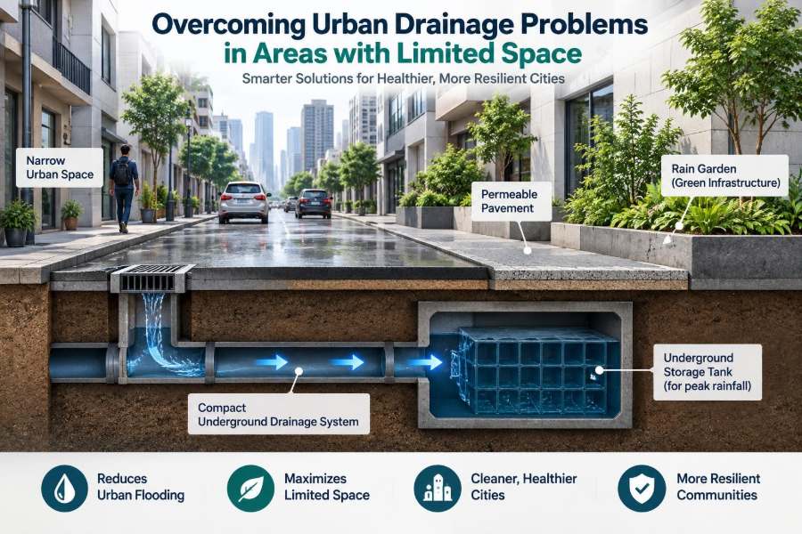

A narrow street floods after a short, intense storm. Water collects at the curb, shop entrances become shallow pools, and pedestrians step around blocked grates. Yet beneath the same street may lie water pipes, telecom ducts, power cables, foundations, and transit infrastructure—with almost no free ground left for a conventional drainage upgrade.
This is a familiar urban engineering problem. Older districts were often drained for smaller paved areas and different rainfall patterns, while redevelopment adds roofs, roads, and hard surfaces that send runoff into already constrained systems.
Solving the problem is not simply a matter of installing a larger pipe. Space, elevation, utilities, maintenance access, receiving-water levels, public safety, and construction disruption all shape what can actually work.
Good compact drainage design treats the street, building, landscape, and underground network as one system. The aim is to manage water where it falls, move unavoidable flows safely, and reduce damage when the network is temporarily overwhelmed.
🌧️ Why tight urban sites flood so easily
Urban flooding occurs when water arrives faster than a site can absorb, store, or convey it. On a compact site, those three functions compete for the same limited area and underground volume.
Paved surfaces shed water quickly, while narrow streets can concentrate flow toward low points. A small blockage at one inlet may then divert water across the carriageway or toward vulnerable doorways.
The challenge is especially acute where development has filled former yards, gardens, or open plots. Lost pervious ground removes both infiltration and surface storage that previously softened storm runoff.
🧭 Start with the full drainage pathway
Before selecting any intervention, map the path from rainfall to its final destination. This includes roof downpipes, gullies, channels, private drains, public sewers, outfalls, nearby watercourses, and overland escape routes.
Plans alone are not enough. A site walk during or soon after rainfall can reveal ponding, gutter flow, blocked grates, reverse slopes, and informal drainage paths that drawings do not show.
- Identify where runoff originates and how quickly it reaches each low point.
- Record levels at thresholds, kerbs, inlets, manholes, and outfalls.
- Locate utility corridors, basements, trees, retaining walls, and foundations.
- Separate confirmed information from assumptions needing survey or investigation.
📏 Survey levels before designing pipes
Drainage is governed by gravity and elevation. A pipe that looks feasible in plan may have insufficient cover, an adverse gradient, or no practical connection point once real levels are measured.
A detailed topographic survey should establish the surface falls that guide runoff. Invert levels—the internal bottom elevations of pipes and chambers—are equally important because they determine whether a new connection can drain by gravity.
Where gravity flow is impossible, designers may consider local storage, a pumped system, or a different discharge route. Pumping can solve a level constraint, but it introduces power, controls, maintenance, and failure-mode requirements.
🏙️ Understand what has changed in the catchment
The drainage catchment is the area contributing water to a point. In dense cities, it often extends beyond the apparent project boundary: an uphill lane, neighboring roofs, or a public road may send flow onto the site.
Redevelopment commonly increases imperviousness even when the building footprint changes little. Replacing a planted courtyard with loading space, for example, can produce a sharper and larger runoff peak.
Assess both present and proposed conditions. The design question is not only “Can this drain?” but “How will this change flows delivered to the local network during a storm?”
🧮 Define a realistic design storm
Rainfall design requires local data, applicable authority requirements, and professional judgment. Different assets may be checked against different storm events because a minor nuisance on a footpath is not equivalent to flooding a building or critical road.
Intensity, duration, storm pattern, antecedent wetness, and climate allowance can all influence results. Short, intense bursts may control small paved courtyards, while longer events may control storage systems and downstream sewers.
Models are useful, but their output is only as reliable as the catchment, levels, pipe condition, and rainfall inputs. Designers should state assumptions clearly rather than treating a calculation as a guarantee.
🚰 Separate runoff from wastewater where possible
Stormwater and wastewater have different hydraulic and public-health consequences. A separate system carries rainfall independently, while a combined system carries both through the same network.
In combined areas, additional runoff can contribute to surcharge, when the pipe or sewer fills and water level rises above its normal operating condition. Misconnections can also send dirty flows to an inappropriate outlet or overload treatment infrastructure.
Existing drainage must be verified by records, tracing, inspection, and local requirements. Pipe appearance, age, or direction alone does not reliably establish what it carries.
🔍 Investigate the existing network
A compact retrofit should not be designed around assumed pipe capacity. Camera inspection can identify cracks, roots, displaced joints, sediment, and illegal connections; jetting or cleansing may restore capacity where blockage is the real problem.
Inspection chambers and manholes help confirm flow direction and levels. However, access limitations, traffic constraints, and buried utilities can leave uncertainty, so the design should include sensible allowances and safe construction-stage verification.
Sometimes a modest repair, inlet reset, or maintenance program provides more benefit than a large new structure. This does not remove the need for capacity assessment, but it prevents expensive work from solving the wrong problem.
🗺️ Protect the overland flow route
Every drainage system has a limit. When inlets block or rainfall exceeds pipe capacity, water follows the ground surface; this is called an overland flow path.
Designers should identify where this water can travel with the least harm. Roads, landscaped corridors, and deliberately graded public spaces may safely convey shallow temporary flow, while basement ramps, stations, substations, and ground-floor entrances require protection.
Trying to trap all exceedance water behind a kerb or wall can create a deeper, more dangerous pond. A planned escape route is often safer than an accidental one.
🧱 Make building thresholds part of the system
A drainage network cannot compensate for poor threshold design. Doorways at or below surrounding pavement level are vulnerable even if nearby pipes are correctly sized.
Useful measures include raised finished-floor levels, local cross-falls away from entrances, linear drains with accessible sumps, and carefully designed ramps. Each solution must still provide accessible movement and avoid creating a trip hazard.
Basement access deserves particular attention. A ramp acts like a channel during intense rainfall, so interception, local storage, backup protection, and a defined emergency response may all be needed.
🕳️ Use compact underground detention
Detention temporarily holds runoff and releases it at a controlled rate. On constrained sites it may use modular geocellular crates, oversized pipes, tanks, or purpose-built chambers below pavements, parking bays, or courtyards.
The key distinction is that detention is not disappearance. It reduces the peak flow sent downstream, provided the outlet control remains functional and the structure has enough volume for the selected design condition.
Underground storage is useful where surface land is unavailable, but it needs inspection access, sediment management, structural design for surface loads, and protection from utility conflicts.
🌿 Use bioretention where soil and space allow
Bioretention systems filter runoff through planted media, usually above a drainage layer. Rain gardens, tree pits, and vegetated curb extensions can slow flow, trap sediment, and improve streetscape conditions while using small areas intelligently.
They are not automatically suitable everywhere. Their performance depends on available footprint, growing conditions, underdrain layout, local soils, groundwater level, contamination risk, and a maintenance plan.
A small bioretention cell works best when it intercepts runoff near its source. Sending all runoff from a large block into a tiny planter may exceed its hydraulic and maintenance capacity.
🌳 Turn street trees into drainage assets
Tree pits can be designed to receive and temporarily store road runoff rather than being isolated by kerbs. With appropriate soil volume, overflow arrangements, root protection, and underdrainage where needed, they can become distributed stormwater features.
The detail must protect both tree health and pavement performance. Compacted soil, inadequate aeration, repeated contaminated inflow, or poorly located inlets can undermine the intended benefit.
Coordination with streetscape and utility teams is essential. A drainage feature that conflicts with roots, sight lines, or maintenance practices is unlikely to perform for its full life.
🧱 Consider permeable paving carefully
Permeable paving allows water to pass through joints or a porous surface into an open-graded sub-base. The sub-base can provide temporary storage, infiltration, or controlled drainage to an outlet.
It can be effective on low-speed areas such as parking spaces, walkways, courtyards, and some lightly trafficked streets. It is less forgiving where heavy loading, fine sediment, or poor construction control could clog voids or damage the pavement structure.
| Approach | Best fit | Main constraint |
|---|---|---|
| Permeable paving | Courtyards, parking, paths | Clogging and load design |
| Underground tank | Very limited surface space | Access and lifecycle maintenance |
| Bioretention | Streetscape and source control | Footprint and plant care |
| Oversized pipe | Linear corridors | Limited treatment value |
💧 Test infiltration instead of assuming it
Infiltration sends water into the ground, but it is appropriate only where ground conditions support it. Soil permeability, seasonal groundwater, slope stability, contamination, and proximity to foundations all need investigation.
Field tests should reflect likely construction conditions rather than an idealized surface layer. Fine soils, compaction, and groundwater can greatly limit infiltration, while variable fill may produce inconsistent performance across a small site.
Where infiltration is uncertain, a lined system with controlled discharge may be more dependable. Infiltration features also need safe overflow paths because no soil system should be expected to absorb unlimited rainfall.
🏗️ Coordinate with buried utilities early
Limited-space drainage is frequently a utility-coordination problem. New tanks and pipes can conflict with water mains, gas lines, electric cables, fiber ducts, district energy systems, and the clearance zones needed to repair them.
Utility records are valuable but may be incomplete or inaccurate. Appropriate detection, trial holes, and consultation with asset owners reduce the risk of redesign after excavation begins.
Vertical stacking is not always a solution. A drain placed beneath another service may become inaccessible, and a deep excavation may disturb adjacent infrastructure or building foundations.
🧰 Select pipes for hydraulics and maintenance
Pipe diameter, gradient, material, junction geometry, and access spacing affect both capacity and cleanability. A pipe that technically carries the design flow may still be a poor asset if it collects sediment and cannot be inspected or cleared.
Very flat grades are common in dense districts because connection depths are constrained. In those cases, careful detailing of chambers, bends, silt control, and flushing access becomes particularly important.
Do not enlarge pipes indiscriminately. A larger pipe can reduce flow velocity under small storms and encourage sediment deposition, while the true bottleneck may be an inlet, downstream sewer, or outfall.
🧹 Design for sediment and litter
Urban runoff carries leaves, grit, packaging, road debris, and construction sediment. These materials reduce inlet capacity and can rapidly degrade small drainage features if there is no pretreatment or maintenance access.
Use sumps, silt traps, forebays, catch pits, or inlet screens where appropriate, but recognize that every capture device needs cleaning. Fine screens can protect downstream systems yet clog quickly if neglected.
A practical question is simple: who can reach this component, with what equipment, and where will removed material go? If that answer is unclear, the detail is incomplete.
🔧 Make maintenance access non-negotiable
Drainage assets often fail quietly. A buried chamber may fill with sediment for years before a severe storm exposes the problem, by which time the original design intent is irrelevant.
Provide safe access points, identifiable covers, inspection ports, isolation where useful, and clear asset records. Access should work after landscaping, street furniture, parked vehicles, and future resurfacing are considered.
For private developments, responsibility must be explicit. Handing over a sophisticated system without an operations plan can transfer a predictable problem to building managers who were never told it existed.
📋 Plan operations from the first sketch
Operation and maintenance should influence layout before the final design, not be added as a note at handover. Define inspection frequency according to asset type, sediment load, vegetation, and observed performance.
An effective plan usually includes seasonal checks, post-storm inspections after unusual events, sediment removal triggers, vegetation care, and a response procedure for blockages or alarms.
- Keep as-built drawings, levels, photographs, and manufacturer information.
- Record inspections and maintenance so recurring problems can be identified.
- Train responsible staff to recognize blocked inlets and unusual standing water.
- Review performance after site changes, resurfacing, or new connections.
🚧 Manage construction-stage drainage
Construction can create the very flooding risk the finished scheme is meant to reduce. Excavations collect water, temporary surfaces alter flow, and exposed soil can send heavy sediment loads into existing drains.
A construction drainage plan should maintain safe routes for runoff, protect inlets, control sediment, and avoid discharging contaminated water without appropriate treatment or approvals. Temporary pumps require backup power and supervision where failure could cause damage.
Final levels should be checked before demobilization. A small paving error near an entrance or gully can defeat an otherwise well-designed drainage system.
🧩 Retrofit in layers rather than seeking one perfect asset
In constrained urban areas, a distributed treatment train is often more practical than a single large intervention. The principle is to use several measures in sequence: source control, local storage, controlled conveyance, and safe exceedance routing.
For a hypothetical narrow commercial street, roof runoff might feed small planters, pavement runoff might enter tree pits and gullies, an underground tank might attenuate remaining flow, and the street profile might guide exceptional runoff away from doorways.
This layered approach provides resilience because the system does not depend entirely on one inlet, tank, or pipe. It also allows upgrades to be phased as streets are renewed or buildings are redeveloped.
⚖️ Balance flood control with water quality
Fast conveyance may reduce local ponding but can send polluted runoff and higher peaks downstream. Conversely, a feature designed mainly for treatment may not provide enough storage for a severe event.
Road runoff can contain sediment, hydrocarbons, metals, and de-icing residues, depending on local conditions. Pretreatment and media selection should match likely pollutants and the receiving environment.
The best solution depends on the site objective: protecting a doorway, limiting downstream discharge, improving water quality, supporting trees, or several of these together. Naming the priority helps resolve design trade-offs honestly.
🌊 Check downstream and outfall constraints
A site can have adequate local storage yet still fail if its outlet is submerged or the receiving sewer surcharges. High water levels in a river, tide-influenced channel, or downstream sewer may prevent normal discharge.
Backflow prevention devices can be valuable, but they may also block the planned outlet during high downstream levels. Upstream storage and a safe emergency overflow route must then accommodate the retained water.
Outfalls should be considered for scour protection, visibility, access, and environmental effects. A pipe endpoint is not merely a drawing symbol; it is an operational interface with a larger system.
🛡️ Build resilience for events beyond the design case
No practical drainage system eliminates all flood risk. Resilience means reducing consequences when conditions exceed expectations, an asset blocks, power fails, or a downstream system is full.
Useful measures include sacrificial floodable spaces, raised critical equipment, watertight service entries, non-return protection where justified, warning procedures, and routes that direct water away from high-consequence areas.
This is a different question from ordinary drainage capacity. Capacity manages anticipated runoff; resilience manages what happens when the anticipated system is exceeded.
👥 Coordinate planners, architects, and operators
Drainage decisions influence land use, street geometry, landscape, accessibility, structural design, and maintenance budgets. If the drainage engineer joins only after levels and utilities are fixed, many low-cost options have already disappeared.
Early collaboration can reserve corridors, protect space for storage, align downpipes with landscape features, and avoid locating entrances at obvious low points. It also makes trade-offs visible before they become expensive site constraints.
Residents, facility managers, and municipal operations teams provide practical insight too. They often know where water actually ponds, which inlets clog, and what equipment can reach a street.
🚫 Avoid common limited-space drainage mistakes
Several recurring choices create avoidable failures:
- Relying on a single low inlet: one blockage can redirect an entire paved area.
- Ignoring finished levels: attractive paving can inadvertently slope water into buildings.
- Installing inaccessible storage: a tank without inspection and cleaning access is a hidden liability.
- Assuming infiltration: unsuitable soils or high groundwater can leave storage full.
- Forgetting overflow: every storage feature needs a safe route when it fills.
- Copying a standard detail: generic details may conflict with local utilities, traffic loads, or maintenance practice.
📈 Monitor performance and adapt
Drainage design improves when observed performance feeds back into operation. Simple inspection records, rainfall observations, photographs, water-level sensors, or flow monitoring can reveal whether a feature drains as intended.
Monitoring is especially helpful for innovative or constrained retrofits, where construction tolerances and uncertain existing networks affect performance. It can also show whether maintenance intervals are too long or whether a specific inlet repeatedly collects debris.
Adaptation may involve resetting a grate, modifying a kerb opening, adding pretreatment, changing planting, or revising maintenance—not necessarily rebuilding the whole system.
💰 Compare lifecycle value, not just installation cost
The cheapest excavation or pipe layout may create high future costs if it requires frequent pumping, difficult access, or disruptive cleaning. Conversely, a feature with a higher initial cost may provide storage, public-realm value, and reduced damage exposure over time.
Lifecycle review should consider construction complexity, utility diversions, inspection, cleaning, renewal, energy use, disruption, and consequences of failure. These factors are particularly significant beneath busy urban streets where future excavation is expensive.
Cost decisions should remain transparent about uncertainty. Early estimates for buried conditions can change once surveys and trial excavations reveal what is actually present.
🧠 A practical design sequence for constrained sites
A disciplined sequence prevents attractive concepts from failing on levels, utilities, or maintenance. Start broad, then narrow choices using evidence.
- Gather records, survey levels, inspect drainage, and walk the site.
- Define catchments, flood pathways, design criteria, and required approvals.
- Test feasible source-control, storage, conveyance, and overflow options.
- Coordinate utilities, structures, landscape, access, and construction constraints.
- Check hydraulics, water quality, exceedance behavior, and downstream conditions.
- Detail access, ownership, commissioning, and long-term maintenance.
- Verify final levels and performance during construction and after storms.
🌉 The core principle: give every drop a planned job
Successful urban drainage in limited space does not depend on one universally best technology. It depends on assigning each portion of runoff a deliberate role: infiltrate where ground conditions permit, store where peaks need moderation, convey where movement is necessary, and overflow where exceedance can occur safely.
That approach turns constraints into design inputs. A tree pit, pavement foundation, roof, kerb line, tank, and street profile can each contribute when they are connected by sound levels, clear maintenance responsibility, and realistic hydraulic assumptions.
The most reliable schemes are therefore understandable as well as technically competent. Operators should know where water goes, how features are accessed, what happens when they fill, and which actions keep them working.
In a crowded city, resilient drainage comes from planning water’s entire journey—not from hiding a larger pipe underground. 🌧️🏙️🔧