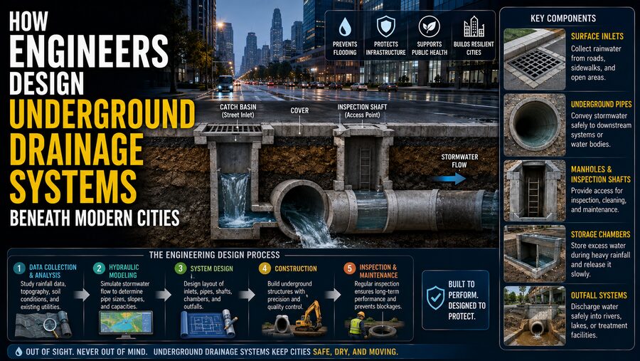

When heavy rain falls on a modern city, enormous volumes of water can reach streets, rooftops, parking lots, sidewalks, rail corridors, and other paved surfaces within minutes. 🌆🌧️ Unlike forests or open soil, these hard surfaces absorb relatively little rainfall, so much of the water becomes stormwater runoff.
If that water were allowed to collect uncontrolled, streets could flood, buildings could be damaged, traffic could stop, and underground infrastructure could become overwhelmed.
The reason many cities remain usable during ordinary storms is largely invisible: beneath the streets lies a carefully engineered network of drains, pipes, tunnels, manholes, storage structures, pumping stations, channels, and treatment systems.
Designing this underground drainage network is far more complicated than simply installing large pipes. Civil engineers must predict how much rain may fall, determine where the water will travel, calculate pipe capacities, work around existing utilities, control flooding risk, protect rivers, and make sure the system can still be maintained decades later. 🏗️💧
🌧️ The First Question: How Much Water Must the System Handle?
Before engineers choose pipe sizes, they need to estimate how much stormwater could enter the drainage system.
This is a hydrology problem.
Engineers study factors such as:
- Rainfall intensity
- Storm duration
- Drainage area
- Ground slope
- Soil conditions
- Percentage of paved surface
- Land use
- Existing waterways
A short, extremely intense thunderstorm may produce a very different drainage problem from a long period of moderate rain.
Historical rainfall records and statistical models help engineers estimate storms of different probabilities.
For example, a city may design different parts of its drainage network for specified design storms depending on local regulations and the consequences of flooding.
🗺️ Cities Are Divided Into Drainage Catchments
Water does not enter one giant citywide pipe.
Engineers divide urban areas into smaller drainage zones known as catchments or watersheds.
Each catchment directs runoff toward particular drains or channels.
Imagine several city blocks.
Rain falling on roofs may flow into gutters.
Street runoff moves toward low points.
Roadside inlets collect the water.
All of these surfaces may eventually drain into one underground pipe.
Engineers calculate the contributing area for each inlet and pipe segment.
As pipes move downstream and receive water from more catchments, the required capacity generally increases.
This is why drainage pipes often become larger farther downstream.
🧮 Estimating Peak Stormwater Flow
For smaller urban catchments, engineers may use simplified hydrologic methods to estimate peak runoff.
One classic concept relates:
Rainfall intensity × Drainage area × Runoff behavior
A heavily paved downtown district produces much more immediate runoff than an equally sized park.
Why?
Because pavement, rooftops, and concrete are relatively impermeable.
Rain cannot easily soak into them.
Vegetated soil, by contrast, can absorb and temporarily store some water.
Engineers represent these differences mathematically when estimating the amount of runoff reaching the drainage network.
For large or complex systems, computer models can simulate how entire storms move across a city over time.
🕳️ Street Inlets Are the Entry Points
Those metal grates and openings along roads are important pieces of hydraulic infrastructure.
They are commonly called:
- Storm drains
- Catch basins
- Gullies
- Inlets
Their job is to capture surface runoff before water becomes deep enough to create dangerous street flooding.
Inlet design must consider:
- Road slope
- Gutter flow
- Inlet spacing
- Expected rainfall
- Debris
- Pedestrian and bicycle safety
If too few inlets are installed, water can bypass them and continue down the street.
Even a large underground pipe cannot help if water cannot enter the system fast enough.
🧹 Catch Basins Can Trap Sediment and Debris
Some drainage inlets include a lower chamber where heavier sediment can settle.
This helps reduce the amount of sand, gravel, and debris entering downstream pipes.
However, these structures require maintenance.
If leaves, litter, or sediment block an inlet, the effective drainage capacity may fall dramatically.
This demonstrates an important engineering principle:
A drainage system must be designed not only to work when new, but also to remain maintainable throughout its operating life. 🔧
📐 Gravity Does Most of the Work
Where possible, urban drainage systems rely on gravity flow.
Engineers install pipes with a slight downward slope so water naturally moves toward lower elevations.
This avoids the need to continuously pump enormous volumes of stormwater.
However, the slope must be selected carefully.
If a pipe is too flat:
- Water moves slowly.
- Sediment may accumulate.
- Capacity may be reduced.
If flow becomes extremely fast, it may create erosion or structural concerns at outlets.
Engineers therefore balance pipe size, slope, flow velocity, and downstream conditions.
🔵 Pipe Diameter Is Determined by Hydraulic Calculations
A pipe must be large enough to carry its expected flow.
Engineers use hydraulic equations and computer models to calculate how water moves through underground conduits.
Important variables include:
- Pipe diameter
- Pipe slope
- Internal roughness
- Water depth
- Flow velocity
A smooth pipe allows water to move differently from a rough or deteriorated one.
The material and age of the pipe therefore matter.
Common drainage pipe materials can include reinforced concrete, various plastics, and other engineered materials depending on diameter and project requirements.
📊 Engineers Track the Hydraulic Grade Line
One critical concept in drainage design is the hydraulic grade line.
It represents the level to which water pressure could rise inside the drainage system.
During ordinary flow, pipes may be only partly filled.
During a major storm, however, downstream restrictions can cause water to back up and pipes may become pressurized.
If the hydraulic grade line rises above a street inlet or manhole, water can emerge onto the surface.
Engineers therefore model the hydraulic grade line throughout the network.
The objective is to understand:
Where will water levels rise during a severe storm?
This helps identify potential flooding locations before construction.
⬇️ Underground Elevation Is Surprisingly Difficult
Urban streets already contain enormous amounts of infrastructure.
Below ground, engineers may encounter:
- Drinking-water pipes 🚰
- Gas lines
- Electrical conduits ⚡
- Telecommunications cables
- District heating systems
- Subway tunnels 🚇
- Foundations
- Existing sewers
The drainage pipe cannot simply go wherever engineers would ideally place it.
It must pass around or beneath these obstacles while maintaining enough slope to keep water moving.
This three-dimensional coordination can become one of the hardest parts of urban infrastructure design.
Modern engineers may use digital mapping and Building Information Modeling tools to identify potential conflicts before excavation begins.
🕳️ Why Cities Have So Many Manholes
Manholes provide access to underground drainage and sewer systems.
They are commonly installed:
- At pipe intersections
- Where pipe direction changes
- Where pipe size changes
- At intervals along long runs
Without access points, inspecting and cleaning underground pipes would be extremely difficult.
Maintenance crews may use manholes to deploy:
- Inspection cameras 📹
- Cleaning equipment
- Pumps
- Measurement devices
Manholes are therefore not merely access holes—they are strategically placed maintenance nodes.
🌊 Stormwater and Sewage Are Not Always the Same System
Cities can use different sewer configurations.
💧 Separate Systems
A storm sewer carries rainwater runoff.
A separate sanitary sewer carries wastewater from homes and businesses toward treatment facilities.
This is common in many modern developments.
🚽 Combined Systems
Some older cities have combined sewers.
The same pipes carry both sewage and stormwater.
During ordinary weather, this can work adequately.
During intense rain, however, the combined volume may exceed pipe or treatment capacity.
This can create serious operational and environmental challenges.
Modern infrastructure projects may therefore include storage tunnels, sewer separation, or other upgrades to reduce overflow risks.
🏙️ Large Underground Storage Tunnels Can Control Flooding
Sometimes increasing every local pipe size would be extremely expensive.
Instead, cities may build enormous underground tunnels or storage chambers.
During heavy rainfall, excess stormwater or combined flow is temporarily diverted into these structures.
After the storm passes, the stored water can be released gradually.
This is essentially a giant underground buffer.
Conceptually:
Heavy storm → Temporary storage → Storm passes → Controlled release
Large tunnel systems can significantly reduce peak flows entering downstream treatment plants or rivers.
🛢️ Detention and Retention Reduce Peak Flow
Not all drainage infrastructure is located directly below streets.
Cities also use detention and retention facilities.
A detention basin temporarily stores stormwater and releases it slowly.
A retention facility may hold water longer or permanently, depending on design.
The basic principle is important:
Rather than sending every drop of rain downstream immediately, engineers intentionally delay part of the flow.
This reduces the peak load on downstream drainage pipes.
🌿 Green Infrastructure Helps Water Stay Near Where It Falls
Modern urban drainage increasingly combines underground pipes with surface-based green infrastructure.
Examples include:
- Rain gardens 🌱
- Bioswales
- Green roofs
- Permeable pavement
- Tree trenches
- Infiltration systems
These features attempt to absorb, store, or slow rainfall before it enters conventional drainage pipes.
Imagine a parking lot made from impermeable asphalt.
Almost all rainfall may become runoff.
Replace part of the surface with permeable material and landscaped infiltration zones, and some rainfall can soak into the ground.
This reduces pressure on underground infrastructure.
🧽 Cities Are Becoming More Like “Sponges”
Some planners use the concept of a sponge city.
Instead of treating rainfall as something that must be removed immediately, the urban landscape is designed to absorb, store, reuse, and slowly release water.
This can include:
Green roofs → Rain gardens → Permeable surfaces → Underground storage → Controlled discharge
Such approaches can reduce flooding while also improving urban environments.
However, soil conditions, groundwater, contamination, maintenance, and climate all affect which techniques are appropriate.
🚧 What Happens When Gravity Is Not Enough?
Sometimes water cannot reach its destination entirely by gravity.
The drainage network may be too deep.
The terrain may be too flat.
A river level may be higher than the pipe outlet.
In these situations, engineers may install a pumping station.
Stormwater enters a wet well or storage chamber.
Large pumps then raise the water to a higher elevation or pressure so it can continue toward its destination.
Because storm flows can be enormous, these pumps may need substantial capacity.
⚙️ Pumping Stations Need Redundancy
Flood protection cannot depend entirely on one pump.
If that pump fails during the storm for which it is most needed, the consequences could be severe.
Pumping stations may therefore use:
- Multiple pumps
- Backup electrical power
- Emergency generators
- Water-level sensors
- Automatic controls
- Alarms
The design may allow some equipment to fail while the station continues operating.
This principle is called redundancy.
🌊 River Levels Can Cause Backflow
Imagine an underground storm drain that empties into a river.
Normally:
City runoff → Pipe → River
But during flooding, the river level may rise above the pipe outlet.
Without protection:
River → Pipe → City
Water could flow backward through the drainage network.
Engineers may install flap gates, check valves, tidal gates, pumps, or other systems to prevent or manage this reverse flow.
Coastal cities must also consider tides and storm surges. 🌊
🌍 Climate Change Complicates Drainage Design
Many cities are reevaluating drainage systems because historical rainfall patterns may no longer be reliable guides to future conditions.
Some regions are experiencing changes in:
- Extreme rainfall intensity
- Storm frequency
- Sea level
- Coastal flooding
- Urban heat and evaporation patterns
At the same time, cities continue adding buildings and pavement.
An area that once contained fields may become densely developed, producing much more runoff.
Engineers therefore increasingly analyze future scenarios rather than relying only on past conditions.
🚨 Drainage Systems Cannot Economically Handle Every Possible Storm
It would be extraordinarily expensive to build pipes large enough for every imaginable rainfall event.
Cities therefore use risk-based design.
Underground pipes may be designed for a certain range of storms, while extreme events are managed through additional surface pathways.
This is sometimes described as the difference between:
Minor drainage system — pipes, inlets, and ordinary storm infrastructure.
Major drainage system — streets, channels, parks, overflow routes, and other pathways used during extreme storms.
A properly designed street may intentionally carry shallow floodwater toward a safer location during a rare event.
The important goal is to keep water away from buildings and critical facilities.
🛣️ Streets Can Become Part of the Flood-Control System
A road is not only a transportation surface.
Its elevation and shape can influence stormwater movement.
Engineers may design:
- Road crowns
- Curbs
- Gutters
- Low points
- Overland flow routes
so that extreme runoff follows predictable pathways.
In a major storm, some temporary street flooding may be acceptable if it prevents water from entering homes, hospitals, subway entrances, or electrical substations.
Urban drainage therefore requires cooperation between roadway engineers, hydrologists, architects, and city planners.
🏥 Critical Infrastructure Gets Extra Protection
Not every location has the same flood consequences.
Flooding an empty parking area is very different from flooding:
- A hospital
- A subway tunnel
- An emergency-response center
- A power substation
- A data center
Engineers therefore pay special attention to critical facilities.
They may use larger drainage capacity, flood barriers, redundant pumps, elevated entrances, or additional storage.
Modern flood engineering is heavily influenced by consequence, not simply probability.
🧪 Water Quality Is Another Design Challenge
Stormwater is not always clean.
As rain flows across streets and industrial areas, it can pick up:
- Oil
- Tire particles
- Sediment
- Metals
- Litter
- Nutrients
- Other pollutants
Allowing all of this material to flow directly into rivers can damage aquatic environments.
Drainage systems may therefore include treatment features such as:
- Sedimentation chambers
- Oil-water separation
- Filters
- Vegetated treatment areas
- Retention ponds
The exact requirements depend on local environmental regulations and site conditions.
🗑️ Trash Can Block Drainage Networks
Plastic bags, leaves, bottles, branches, and other debris can significantly reduce drainage capacity.
Cities use measures such as:
- Grated inlets
- Trash screens
- Debris traps
- Routine street cleaning
Maintenance is critical before and during rainy seasons.
A drainage system with excellent hydraulic calculations can still flood if its entrances are physically blocked.
📹 Engineers Inspect Pipes With Cameras
Large parts of urban drainage systems are difficult or unsafe for people to inspect directly.
Maintenance teams commonly use remotely operated cameras.
A camera travels through the pipe and records:
- Cracks
- Joint failures
- Root intrusion
- Sediment deposits
- Corrosion
- Blockages
This allows engineers to evaluate underground infrastructure without excavating entire streets.
Data from these inspections can be used to prioritize repairs.
🤖 Sensors Are Creating Smarter Drainage Systems
Modern cities increasingly use sensors to monitor drainage infrastructure in real time.
Sensors can measure:
- Water level
- Flow
- Rainfall
- Pump operation
- Gate position
Data can be transmitted to a central control system.
A smart drainage network might dynamically control storage gates or pumps based on an approaching storm.
For example:
Upstream storage available → Hold water temporarily
Downstream capacity improves → Release water gradually
This turns a passive pipe network into a partially adaptive infrastructure system. 📡
🧱 Old Pipes Can Be Rehabilitated Without Full Excavation
Digging up busy streets is disruptive and expensive.
Fortunately, some deteriorated underground pipes can be rehabilitated using trenchless technologies.
One example is cured-in-place pipe lining.
A flexible liner is inserted into the existing pipe and hardened to create a new pipe-like surface inside it.
Other trenchless methods can repair or replace underground pipes while reducing surface excavation.
These techniques are particularly valuable beneath:
- Major roads
- Railways
- Dense commercial districts
- Historic neighborhoods
🚇 Deep Tunnels May Require Tunnel-Boring Machines
When drainage tunnels must pass far beneath dense urban areas, conventional open excavation may be impossible.
Engineers can use tunnel-boring machines.
These enormous machines excavate underground while installing structural tunnel lining behind them.
A deep tunnel can pass below roads, buildings, utility networks, and sometimes subway infrastructure with relatively limited surface disruption.
However, such projects require extensive geological investigation.
Engineers must understand:
- Soil
- Rock
- Groundwater
- Existing foundations
before tunneling begins.
💧 Groundwater Creates Its Own Challenges
Underground construction may encounter groundwater.
Excavating below the groundwater table can cause water to enter trenches or tunnels.
Engineers may need:
- Dewatering wells
- Pumps
- Watertight supports
- Ground treatment
However, removing too much groundwater can also cause nearby soil settlement.
In dense cities, even small ground movements can affect neighboring buildings.
Underground drainage construction is therefore closely connected to geotechnical engineering.
🧱 Pipes Must Survive Loads From Above
A buried drainage pipe does not only carry water.
It must also survive external loads.
These can include:
- Weight of soil
- Cars 🚗
- Trucks 🚛
- Construction equipment
- Nearby foundations
Engineers consider burial depth, soil behavior, pipe stiffness, and installation quality.
A pipe installed beneath a major highway may require different structural design than one beneath a landscaped park.
📏 Construction Accuracy Matters
Gravity systems depend on elevation.
A pipe designed with a small slope can lose much of that slope if installed inaccurately.
Surveyors therefore carefully control:
- Pipe invert elevations
- Manhole positions
- Gradients
- Alignment
Modern construction can use laser levels, digital surveying equipment, and 3D machine guidance.
Even a small elevation error can create a low spot where sediment accumulates.
🧠 Computer Models Simulate Entire City Networks
Large drainage systems contain thousands of pipes and structures.
Engineers use specialized software to simulate how rainfall moves through the network.
A model may represent:
Rainfall → Surface runoff → Inlets → Pipes → Storage → Pumps → River
The simulation can show:
- Which pipes become full
- Where manholes surcharge
- Where streets flood
- How long flooding lasts
- How storage changes peak flow
Engineers can then test different improvements virtually.
For example:
Option A: Increase pipe diameter
Option B: Add detention storage
Option C: Add pumping capacity
The model helps compare effectiveness before expensive construction begins. 💻🌧️
🔄 Drainage Design Is a System Optimization Problem
Making every pipe larger is rarely the best answer.
Large pipes cost more and can require deeper excavation.
A more efficient solution may combine:
- Strategic pipe enlargement
- Additional inlets
- Underground storage
- Green infrastructure
- Pumping
- Surface overflow routes
The goal is to improve the performance of the entire drainage system rather than simply maximizing each individual component.
🏙️ A Simplified Example of Urban Drainage Design
Imagine engineers are designing drainage for a new city district.
Their process might look like this:
1. Map the terrain and proposed development. 🗺️
2. Divide the area into drainage catchments.
3. Estimate rainfall runoff. 🌧️
4. Locate street inlets.
5. Determine pipe routes and slopes.
6. Calculate required pipe capacities. 📐
7. Check hydraulic grade levels.
8. Coordinate around water, gas, electrical, and transit infrastructure.
9. Add detention or green infrastructure where useful. 🌱
10. Simulate extreme storm events.
11. Provide safe overflow routes.
12. Design inspection and maintenance access. 🔧
The final system may be almost invisible after construction, but its design requires multiple engineering disciplines working together.
✅ Final Thoughts
Underground drainage systems are among the most important pieces of infrastructure beneath modern cities. 🌆💧
Their purpose is simple—move unwanted water away safely—but achieving that goal requires sophisticated engineering.
Engineers must understand rainfall, hydrology, surface runoff, pipe hydraulics, terrain, groundwater, structural loads, environmental quality, pumping, maintenance, and flood risk.
They design street inlets to capture runoff, gravity pipes to transport it, manholes for access, storage systems to reduce peak flows, and pumping stations where gravity cannot do the job.
They must also work around an underground maze of existing utilities while planning for storms that may become more severe in the future.
Increasingly, cities combine conventional underground pipes with green infrastructure, smart sensors, real-time controls, detention systems, and resilient surface flood routes. 🌱📡
The most effective urban drainage system is therefore not simply the biggest pipe network.
It is a coordinated system that manages water at multiple levels:
Capture it → Slow it → Store it → Move it → Treat it → Release it safely.
Most people rarely notice this infrastructure when it works correctly.
And that is precisely the point.
Beneath the roads and sidewalks, thousands of interconnected structures quietly manage each storm—helping keep homes dry, transportation moving, businesses operating, and modern cities functioning even while enormous volumes of rainwater move beneath our feet. 🌧️🏙️🛠️