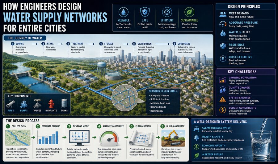

Every time someone opens a faucet, fills a glass, takes a shower, runs a washing machine, or uses a fire hydrant, a vast network of pipes, pumps, tanks, valves, treatment facilities, and sensors is working behind the scenes. 🚰🏙️
Designing a water supply network for an entire city is one of the most important tasks in civil and environmental engineering.
A city cannot simply connect every building to one giant pipe and hope for the best. Engineers must ensure that enough clean water reaches thousands or millions of people at the correct pressure, even when demand changes dramatically throughout the day.
The system must also remain reliable during:
- Pipe failures
- Fires 🔥
- Power outages ⚡
- Population growth
- Droughts
- Maintenance work
- Seasonal demand changes
The basic objective can be summarized as:
Water source ➡️ treatment ➡️ storage ➡️ transmission ➡️ distribution ➡️ consumers
But designing each part requires careful analysis of geography, population, hydraulics, public health, economics, and future growth.
🌊 Step 1: Find a Reliable Water Source
Every urban water system begins with a source.
Cities may obtain water from:
- Rivers
- Lakes
- Reservoirs
- Groundwater aquifers
- Mountain catchments
- Desalination plants
- Recycled water systems
Engineers first evaluate how much water the source can provide safely and reliably.
A river may contain plenty of water during rainy months but much less during drought.
An aquifer may provide excellent water but can become depleted if groundwater is pumped faster than it is naturally replenished.
Therefore, engineers examine long-term water availability, not merely today’s supply.
A growing city may require several independent sources to reduce the risk of shortages. 🌍
🧮 Step 2: Estimate How Much Water the City Will Need
Before designing pipes, engineers must estimate demand.
This involves determining how much water residents, businesses, industries, public institutions, and emergency services are likely to use.
A simplified estimate might begin with:
Population × average daily consumption per person
Suppose a city has 500,000 residents and average domestic consumption is 150 liters per person per day.
Residential demand alone would be:
500,000 × 150 = 75,000,000 liters per day
or:
75 million liters per day
But that is only the beginning.
Engineers must also include water for:
🏥 Hospitals
🏫 Schools
🏭 Industry
🏢 Offices
🌳 Parks
🚒 Firefighting
🧹 Municipal cleaning
💧 System losses
The total design demand may therefore be substantially larger.
📈 Average Demand Is Not Enough
Water consumption is not constant.
Demand usually varies throughout the day.
Early morning may bring a strong increase as people shower, prepare food, and get ready for work.
Demand may decrease during midday and rise again during evening hours.
Therefore, engineers distinguish between:
Average daily demand
Maximum daily demand
Peak hourly demand
A network designed only for the average flow could experience low pressure during busy periods.
For example:
Average demand: 100 million liters/day
Peak-hour equivalent demand: much higher
Pipes, pumps, and storage facilities must be capable of handling these peaks.
🏙️ Engineers Also Design for Future Population Growth
A water network may operate for many decades.
Engineers therefore cannot design only for the current population.
They use demographic projections to estimate future demand.
If today’s population is:
500,000
but the city may grow to:
800,000
within several decades, the infrastructure should either be sized for future needs or designed so that it can be expanded economically.
Otherwise, new neighborhoods may eventually suffer poor pressure or insufficient supply.
Urban planning and hydraulic engineering must therefore work together. 🏗️
🧼 Step 3: Treat the Water
Raw water from rivers, lakes, and groundwater sources may contain:
- Suspended particles
- Microorganisms
- Organic matter
- Dissolved minerals
- Chemical contaminants
Before distribution, the water is treated according to applicable health standards.
A conventional treatment process may include:
Coagulation ➡️ flocculation ➡️ sedimentation ➡️ filtration ➡️ disinfection
Other systems may use:
- Activated carbon
- Membranes
- Ozonation
- UV disinfection
- Reverse osmosis
The finished water then enters the city’s distribution system.
Maintaining water quality remains important even after treatment because the water may spend hours or days traveling through pipes and storage facilities. 🧪
🏞️ Elevation Is Extremely Important
Water pressure depends strongly on elevation.
A neighborhood in a valley may naturally experience much higher pressure than a neighborhood on top of a hill.
A useful relationship is:
Pressure ≈ density × gravity × height difference
This means water located at a higher elevation stores gravitational potential energy.
That is why many cities use elevated tanks or reservoirs.
If a tank is placed high above the buildings it supplies, gravity can generate useful water pressure without continuously running pumps.
Conceptually:
High-level reservoir ➡️ gravitational pressure ➡️ homes below
This makes topography a critical part of network design. ⛰️
🏗️ Step 4: Create Pressure Zones
A city with large elevation differences is often divided into pressure zones.
Each zone operates within a suitable pressure range.
Imagine a city extending from sea level to hillside neighborhoods hundreds of meters higher.
If the entire city were connected to the same hydraulic pressure, lower neighborhoods might experience dangerously high pressure while upper areas receive too little.
Instead, engineers create separate zones using:
- Reservoirs
- Booster pumps
- Pressure-reducing valves
- Control valves
- Separate distribution mains
This allows each area to receive adequate pressure without overstressing pipes and household plumbing.
🛢️ Step 5: Use Storage Tanks and Reservoirs
Water storage is essential.
Demand fluctuates constantly, while treatment plants and major pumps often operate more efficiently at relatively steady rates.
Storage facilities act as buffers.
During low demand:
Production > consumption ➡️ tank fills
During peak demand:
Consumption > production ➡️ tank supplies extra water
Storage therefore smooths the difference between supply and demand. 🔄
Reservoirs can also provide emergency water during:
- Pump outages
- Power failures
- Pipe repairs
- Fires
- Temporary treatment problems
In many systems, storage is one of the main reasons water continues flowing even if part of the infrastructure temporarily stops operating.
🔥 Firefighting Can Determine Pipe Size
Ordinary household demand is not always the largest design condition.
Firefighting may require very high flows over a short period.
Fire hydrants must be able to deliver substantial amounts of water while keeping enough pressure in the rest of the network.
Engineers therefore perform fire-flow analysis.
They may simulate:
Normal demand + major hydrant flow
and check whether nearby pressures remain acceptable.
A pipe that is perfectly adequate for household use might be too small to supply a major firefighting demand.
This is one reason urban water mains are often larger than everyday consumption alone would suggest. 🚒
🚰 Step 6: Design the Pipe Network
Cities contain several classes of pipes.
Transmission Mains
These large pipes carry substantial flows from treatment facilities, reservoirs, or pumping stations toward major parts of the city.
Distribution Mains
These carry water through neighborhoods.
Service Connections
These smaller pipes connect individual buildings to the distribution mains.
Pipe materials may include:
- Ductile iron
- Steel
- PVC
- HDPE
- Reinforced materials
Material selection depends on pressure, soil conditions, corrosion risk, installation method, diameter, cost, and expected service life.
🔄 Why Networks Usually Form Loops
A simple water system could be arranged like a tree:
Main pipe ➡️ smaller branch ➡️ smaller branch
This is called a branched or dead-end network.
However, cities often prefer looped networks.
In a looped arrangement, water can reach a location through more than one route.
For example:
Path A ➡️ neighborhood
and
Path B ➡️ same neighborhood
This provides several advantages.
If one pipe fails, water may still reach customers from the opposite direction.
Loops also help improve pressure distribution and reduce stagnant dead ends.
The same concept is similar to redundancy in electrical grids and computer networks. 🔁
📉 Friction Causes Pressure Loss
As water flows through pipes, friction causes energy loss.
The longer and narrower the pipe, the greater the pressure loss for a given flow.
Engineers commonly use equations such as the Hazen-Williams equation or Darcy-Weisbach equation to estimate these losses.
In general:
Longer pipe ➡️ greater friction loss
Smaller diameter ➡️ much greater friction loss
Higher flow ➡️ greater friction loss
This creates an important design trade-off.
Large pipes reduce friction and improve pressure but cost more to purchase and install.
Small pipes are cheaper but may create poor pressure and high pumping costs.
The engineer must find an economical balance. 💰
⚙️ Step 7: Add Pumping Stations Where Gravity Is Not Enough
Gravity cannot serve every location.
Pumps are required when water must be moved:
- Uphill
- Across long distances
- Into elevated storage tanks
- Through high-pressure zones
A pumping station may contain several pumps rather than one large unit.
For example:
Pump 1: low demand
Pump 1 + Pump 2: normal high demand
Pump 1 + Pump 2 + Pump 3: peak demand or emergency
This arrangement allows the system to match pumping capacity to demand.
It also provides redundancy if one pump fails.
🎛️ Variable-Speed Pumps Improve Efficiency
Older pumping systems often ran pumps at fixed speed and controlled pressure using valves or pump switching.
Modern systems increasingly use variable-frequency drives, or VFDs.
A VFD changes motor speed.
If demand is low:
Pump speed decreases ➡️ energy use falls
If demand rises:
Pump speed increases ➡️ pressure maintained
Because pumping is a major operating cost for many utilities, efficient pump control can save substantial electricity. ⚡💧
🧠 Step 8: Build a Hydraulic Computer Model
Modern city networks are too complex to design entirely by hand.
Engineers create computerized hydraulic models containing:
- Pipes
- Junctions
- Pumps
- Valves
- Reservoirs
- Storage tanks
- Demand patterns
Each pipe is assigned properties such as:
Length
Diameter
Roughness
Elevation
The software calculates how water flows through the network and what pressure exists at each location.
A model may contain thousands or even hundreds of thousands of network elements. 💻
⚖️ Conservation Laws Control the Model
Hydraulic network models rely on fundamental physical principles.
At a pipe junction, conservation of mass requires:
Water entering = water leaving + local demand
The model must also account for conservation of energy.
Pressure energy is lost through friction and altered by:
- Pumps
- Elevation changes
- Valves
- Tanks
By solving these equations simultaneously, the software determines the flow rate in each pipe.
🧪 Engineers Test Many Scenarios Virtually
Once the hydraulic model is built, engineers can test scenarios before modifying the real city.
They may ask:
What happens during peak morning demand?
What if a major pipe breaks?
Can two hydrants operate simultaneously?
What happens if one pumping station loses power?
Will a new housing development have adequate pressure?
What happens if a reservoir is taken offline?
Computer simulations help identify weak areas and prioritize upgrades. 📊
🛑 Valves Allow Sections to Be Isolated
A water network must be maintainable.
If every pipe were permanently connected without isolation valves, repairing one break could require shutting down water across a huge area.
Engineers install valves so sections can be isolated.
When a pipe bursts:
Close selected valves ➡️ isolate damaged section ➡️ maintain service elsewhere
Good valve placement can dramatically reduce the number of customers affected by repairs.
Utilities also need accurate records showing exactly where valves are located and which pipes they control. 🔧
📡 Sensors Help Operators Monitor the Network
Modern water utilities increasingly use sensors and telemetry.
These systems may monitor:
- Pressure
- Flow
- Tank level
- Pump status
- Water quality
- Valve position
Information is often sent to a central SCADA system—Supervisory Control and Data Acquisition.
Operators can then see the condition of the network in near real time.
For example:
Reservoir level falling too quickly ➡️ investigate high demand or possible leak
Sensors make large networks more observable and easier to control. 📡💻
💦 Leakage Is a Major Design and Management Problem
Not all treated water reaches customers.
Some escapes through:
- Pipe cracks
- Broken joints
- Corroded mains
- Faulty service connections
- Leaking valves
This is often included within non-revenue water, which may also include metering inaccuracies and unauthorized consumption.
Utilities can divide networks into district metered areas and compare how much water enters each zone with expected consumption.
If nighttime flow remains unusually high when normal demand is low, hidden leakage may be present. 🔍💧
Reducing leaks saves both water and the energy used to treat and pump it.
🧫 Water Quality Must Be Protected Inside the Network
The job is not finished once treated water enters the pipes.
Utilities must keep water safe until it reaches consumers.
Potential problems include:
- Low disinfectant residual
- Contamination through pipe breaks
- Long water residence times
- Biofilm growth
- Sediment accumulation
- Cross-connections
Engineers therefore consider water age and flow patterns.
A large oversized pipe might provide excellent hydraulic capacity but cause water to move too slowly, increasing residence time.
This illustrates another design trade-off:
Bigger is not always better.
🔨 Water Hammer Can Damage Pipes
Rapid changes in flow can create pressure waves known as water hammer.
For example, if a large pump stops suddenly or a valve closes too quickly, moving water decelerates rapidly.
Because water has mass, this change can generate a strong pressure surge.
The pressure wave travels through the pipe network and may damage:
- Pipes
- Valves
- Pumps
- Fittings
Engineers control water hammer using:
- Slow-closing valves
- Surge tanks
- Air chambers
- Pressure vessels
- Controlled pump shutdown procedures
Transient hydraulic analysis is especially important for large transmission systems. ⚠️
🧱 Pipe Age and Corrosion Affect Long-Term Planning
Water networks can remain in service for many decades.
Older cities may have pipes installed generations ago.
As pipes age, they may experience:
- Internal corrosion
- External corrosion
- Mineral deposits
- Increased roughness
- Structural weakening
- More frequent breaks
Utilities maintain asset-management programs to determine which pipes should be replaced first.
Replacement decisions may consider:
Age + break history + material + consequence of failure + customer impact
A large transmission main near a hospital may receive higher priority than a small pipe serving a low-demand street.
🌱 Sustainability Is Becoming Increasingly Important
Modern water network design increasingly considers sustainability.
Utilities seek to:
🌱 Reduce leakage
⚡ Reduce pumping energy
💧 Conserve water
♻️ Reuse treated wastewater where appropriate
☀️ Use renewable energy for pumping
📊 Improve demand forecasting
Some cities use separate recycled-water networks for irrigation or industrial uses.
This reduces demand on drinking-water supplies.
Climate change and drought risk are also making long-term resilience more important in many regions.
🚨 Designing for Emergencies
A well-designed city network should continue operating when individual components fail.
Engineers may provide:
- Multiple water sources
- Looped pipelines
- Backup generators
- Redundant pumps
- Emergency storage
- Interconnections between pressure zones
Suppose one major treatment plant goes offline.
If another source and transmission route can temporarily supply the city, the system is far more resilient.
This philosophy is called redundancy.
The same principle appears throughout critical infrastructure:
Do not rely on one component when failure would affect an entire city. 🛡️
🏙️ Expanding the Network for New Development
When a new neighborhood is planned, engineers determine whether the existing system can support it.
The new development may add:
- Residential demand
- Commercial demand
- Fire-flow requirements
- Higher-elevation customers
The hydraulic model is updated to include the new area.
If pressures become too low, possible solutions include:
- Larger mains
- Additional storage
- New booster pumps
- A new pressure zone
- Upgraded transmission pipelines
This helps cities coordinate infrastructure investment with urban growth.
💰 Economics Shape Every Design Decision
Engineers rarely choose the technically largest or strongest option.
They must balance reliability with cost.
For example:
Very large pipe: expensive construction, low friction
Small pipe: cheap construction, high friction and possible pressure problems
A larger pipe may cost more initially but reduce pumping energy for decades.
Engineers therefore consider life-cycle cost, not merely construction cost.
This can include:
- Capital cost
- Energy cost
- Maintenance
- Repair frequency
- Expected service life
- Replacement cost
The best design is often the one that performs reliably at the lowest total long-term cost.
🧭 The Complete Urban Water Supply Process
A simplified city-scale water system works like this:
1. Source water collected 🌊
2. Water treated 🧪
3. Treated water pumped or gravity-fed into storage 🛢️
4. Transmission mains carry large flows across the city 🚰
5. Pressure zones regulate hydraulic conditions 📏
6. Distribution mains deliver water into neighborhoods 🏘️
7. Service connections supply individual buildings 🏠
8. Sensors and SCADA monitor performance 📡
9. Storage and backup systems handle peaks and emergencies 🛡️
Every component must work together.
🏁 Conclusion
Designing a water supply network for an entire city is a complex engineering problem involving much more than choosing pipe sizes. 💧🏙️
Engineers must predict how much water people will use, how demand will change throughout the day, where future neighborhoods will grow, and how elevation affects pressure.
They must select reliable water sources, design treatment systems, locate reservoirs, size pumps, divide the city into pressure zones, and create pipe networks capable of supplying ordinary demand and emergency fire flows.
Hydraulic models allow engineers to simulate thousands of interconnected pipes and ask what happens when conditions change.
If a pipe fails, can another route supply the neighborhood?
If demand suddenly increases, will pressure remain acceptable?
If a pump loses power, is there enough storage?
If a new development is built, can the existing network support it?
These questions define the engineering of resilient urban water systems.
The fundamental principle is:
Deliver enough safe water, at the right pressure, to every customer—while remaining reliable under both normal and abnormal conditions.
When that design succeeds, the result feels remarkably simple to the public.
Someone turns a faucet.
Clean water appears immediately. 🚰✨
Behind that everyday moment is an enormous, carefully engineered network operating continuously beneath the streets—one of the essential systems that makes modern city life possible. 🌍🏙️💧