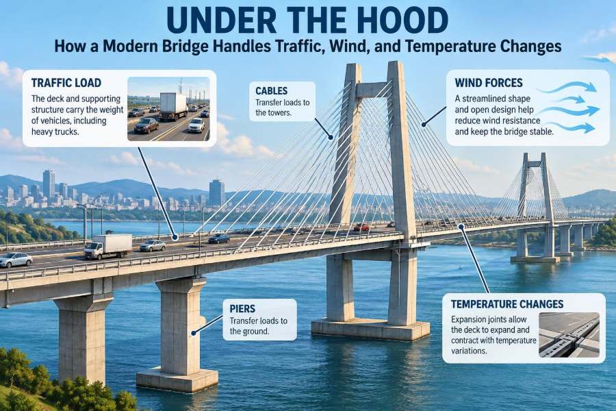

A bridge can look motionless while thousands of vehicles pass over it every day. From the driver’s seat, it is simply a route across a river, valley, rail corridor, or busy road. Beneath the pavement, however, the structure is continually responding to changing forces.
A truck enters a span, gusts push against its side, sunlight warms one end more than the other, and the deck expands by a small but meaningful amount. None of these actions is unusual. A safe bridge is designed precisely because they are expected.
The engineering challenge is not to make a bridge perfectly rigid. It is to provide a deliberate, reliable path for forces to travel from the roadway into the ground, while allowing controlled movement where movement is unavoidable.
Understanding that hidden system helps explain why bridges have joints, bearings, deep foundations, drainage details, inspection platforms, and sometimes even closures during exceptional wind or weather. Modern bridge performance is less about resisting one dramatic event than managing many ordinary actions over decades.
🧭 A Bridge Is a Load-Transfer System
At its most basic, a bridge carries loads from the deck to supports and then into the earth. The deck receives vehicle loads; girders, trusses, arches, or cables distribute them; piers and abutments transfer them into foundations.
This continuous path is called the load path. Engineers check that every major force has a clear route through members, connections, bearings, and soil or rock. A strong individual beam is not enough if its connection or support cannot transfer the force safely.
🚗 What Counts as Traffic Load?
Traffic load includes much more than the static weight of cars and trucks parked on a bridge. It includes vehicle movement, lane position, braking, acceleration, and the possibility that several heavy vehicles occupy a critical part of the span at once.
Design loading represents demanding but realistic traffic conditions rather than an average afternoon. The exact loading models depend on the governing design code, bridge type, road classification, and jurisdiction.
- Dead load: the bridge’s own permanent weight, including structural members, pavement, barriers, utilities, and fixed equipment.
- Live load: movable loads such as vehicles, pedestrians, and sometimes cyclists.
- Dynamic effects: additional response caused by moving vehicles and uneven road surfaces.
⚖️ Why Lane Position Changes the Result
A vehicle does not need to sit at the center of a bridge to create the most demanding effect. A heavily loaded truck near one edge can cause torsion, or twisting, in the deck and its supporting girders.
Engineers place design vehicles in different lanes and at different locations along a span to identify maximum bending, shear, reaction, and torsion. This is why the bridge is analyzed as a three-dimensional system, not merely as a single beam under a centered load.
📈 Bending: The Bridge’s Familiar Internal Force
When a simply supported beam carries load near its middle, it tends to sag. The upper region is compressed and the lower region is stretched in tension. This internal action is bending moment.
Steel, reinforced concrete, prestressed concrete, and timber bridges each manage bending differently. Reinforcing steel is placed where concrete would otherwise crack in tension, while prestressing intentionally compresses concrete so it can remain effective under service loads.
✂️ Shear and Why Supports Need Special Attention
Shear is the internal action that tries to make one portion of a member slide past another. In a typical beam span, shear forces are often highest close to supports, even though bending moment may be greatest near midspan.
This distinction matters in detailing. A girder that has ample bending capacity still needs sufficient web thickness, shear reinforcement, stiffeners, or other measures near bearings and concentrated loads.
🚚 Moving Trucks Create Moving Force Patterns
A truck crossing a bridge does not produce one fixed loading case. As its axles move, the location of maximum bending or shear moves too. Engineers use influence lines and structural analysis software to determine which axle positions create the critical response at a particular point.
For a short span, a single heavy axle can govern a local effect. For a longer bridge, a group of axles or multiple vehicles may produce the more severe global response. The governing case depends on span length, continuity, structural form, and member being checked.
🛞 Dynamic Allowance Is Not an Extra Guess
A vehicle load arrives with motion. Tires pass over surface irregularities, suspension systems oscillate, and a bridge vibrates slightly as axles cross it. Design methods account for this using a dynamic load allowance or related code-based provisions.
This does not mean every truck doubles its effect through impact. It recognizes that a moving load can cause a larger response than the same vehicle placed gently and statically on the deck. Maintaining a smooth deck surface also helps reduce these repeated dynamic demands.
🧱 The Deck Does More Than Provide Pavement
The deck is the roadway surface, but structurally it may act as a slab spanning between girders, a component of a composite steel-concrete system, or a key element in distributing wheel loads.
In many steel girder bridges, shear connectors join the concrete deck to the steel girders. Once the concrete has gained adequate strength, the elements can act together as a composite section, increasing stiffness and bending resistance compared with unconnected components.
🔩 Girders, Trusses, Arches, and Cables Choose Different Paths
Bridge form affects how forces travel. Girder bridges primarily carry loads through bending and shear. Trusses arrange members so many forces are mainly axial tension or compression. Arches direct substantial load as compression toward their supports, while cable-supported bridges use tensioned cables and compression in towers or deck elements.
No form is automatically superior. Span length, foundation conditions, construction access, aesthetics, maintenance capability, cost, clearance requirements, and environmental constraints all influence the appropriate choice.
| Structural form | Primary force behavior | Common practical fit |
|---|---|---|
| Girder bridge | Bending and shear in girders | Short to medium spans with straightforward construction |
| Truss bridge | Axial tension and compression in members | Longer spans where member depth is acceptable |
| Arch bridge | Compression with horizontal thrust at supports | Sites with strong abutments or suitable foundations |
| Cable-supported bridge | Tension in cables, compression in towers | Long crossings where few intermediate supports are desired |
🏗️ Piers and Abutments Are Not Just “Legs”
Piers support the bridge at intermediate locations, while abutments support the ends and retain the approach embankment. Both must resist vertical reactions as well as horizontal actions from braking, wind, thermal movement, earth pressure, and sometimes water or ice.
The geometry of these supports affects structural behavior. A tall slender pier may be more flexible than a short broad one, changing how earthquake, wind, and temperature forces are shared across the bridge.
🌍 Foundations Deliver Loads to the Ground
Every load path ends in soil or rock. Spread footings may work where competent ground lies near the surface. Deep foundations, such as driven piles or drilled shafts, are used when surface material is too weak, compressible, scour-prone, or otherwise unsuitable.
Geotechnical investigation is therefore central to bridge design. Engineers need to understand bearing capacity, settlement, groundwater, slope stability, seismic conditions where relevant, and the possibility that riverbed material may be removed during floods.
🌊 Scour Can Change a Foundation’s Conditions
Scour is the removal of sediment around piers and abutments by flowing water. A foundation that is adequately embedded under ordinary conditions can lose lateral support or become exposed if a flood reshapes the channel bed.
Bridge engineers assess hydraulic conditions and may use deeper foundations, armoring, guide banks, monitoring, or channel-protection measures. The appropriate strategy depends on the river, the foundation type, and the likely evolution of the channel over time.
🌬️ Wind Acts on More Than the Side of the Bridge
Wind produces horizontal pressure on the deck, barriers, vehicles, cables, towers, and maintenance equipment. It can also create vertical uplift or downward pressure, depending on deck shape and wind direction.
The resulting forces must travel through lateral bracing, diaphragms, cross-frames, bearings, piers, and foundations. For a wide bridge, wind may act differently across the deck; for a tall bridge, wind effects on towers and piers can become particularly significant.
🎵 Vibration Is About Frequency as Well as Force
Every structure has natural frequencies: rates at which it tends to vibrate when disturbed. Wind, traffic, pedestrians, and machinery can excite those modes to varying degrees.
The concern is not simply whether a bridge moves. Small, controlled movement is normal. Engineers evaluate whether motion could become uncomfortable, cause fatigue in details, interfere with components, or in rare cases interact unfavorably with aerodynamic forces.
🌀 Aerodynamic Stability Requires Shape Awareness
Wind flowing around a bridge deck can create fluctuating pressures and vortices. For long, flexible spans, aerodynamic behavior becomes a major design topic rather than a minor load calculation.
Engineers may use wind-tunnel testing, computational analysis, carefully shaped deck edges, fairings, dampers, or tuned devices. The objective is to avoid unstable motion such as flutter, where aerodynamic forces can feed energy into structural vibration.
🚧 Why Wind Restrictions May Be Sensible
Temporary restrictions during strong winds do not necessarily indicate that a bridge is near structural failure. High-sided vehicles, motorcycles, pedestrians, and maintenance crews can face hazards at wind speeds well below those that threaten the main structure.
Operational decisions consider local wind measurements, gust patterns, vehicle type, bridge exposure, and agency procedures. Separating user safety thresholds from structural design capacity prevents misleading conclusions about a closure.
🌡️ Materials Expand and Contract Every Day
Steel and concrete change length as their temperature changes. On a long bridge, even a modest temperature change can create movement large enough to matter at joints, bearings, barriers, utilities, and approach slabs.
This behavior is predictable. The problem arises when a bridge is restrained from moving as intended, or when its components do not accommodate different temperature responses consistently.
↔️ Expansion Joints Create Space for Movement
An expansion joint is a controlled gap or movement device between bridge segments or at an abutment. It allows deck movement while maintaining a rideable surface for traffic.
Joints are exposed to water, salt, debris, tire impact, and repeated movement, making them frequent maintenance items. A leaking or damaged joint can allow water to reach bearings, beam ends, and substructure concrete, where deterioration becomes much more costly to address.
🧩 Bearings Separate Support from Restraint
Bearings sit between the superstructure and its supports. They transfer vertical loads while allowing, guiding, or restraining movement and rotation according to the design.
A bridge often has a combination of fixed and expansion bearings. Fixed bearings provide a reference point for longitudinal forces; expansion bearings permit thermal movement. The layout must be coordinated so temperature forces do not accumulate unpredictably in piers or abutments.
🧊 Temperature Is Not Uniform Across a Bridge
A bridge does not warm and cool evenly. Sunlight can heat the top of a concrete deck while the underside remains cooler. One side may be shaded, and steel components can respond quickly to direct solar exposure.
These differences create thermal gradients, which can cause curvature and internal stresses even when the average bridge temperature changes little. Designers consider code-defined thermal cases, but actual site conditions can be complex, especially for unusual geometry or materials.
🛤️ Approach Slabs Manage the Transition to the Road
The roadway leading to a bridge is supported by soil, while the bridge deck is supported by a structure. Because these systems settle and move differently, drivers may notice a bump at the bridge end.
Approach slabs help bridge that transition. Good drainage, well-compacted backfill, suitable joint detailing, and attention to embankment behavior are equally important; an approach slab cannot solve every settlement problem by itself.
🧂 Water and Chlorides Often Drive Deterioration
Water is one of the most persistent threats to bridge durability. It can carry chlorides from deicing salts or marine exposure into concrete, contributing to reinforcement corrosion. Freeze-thaw cycling can worsen cracking and surface damage in cold climates.
Durable design includes drainage slopes, deck waterproofing where appropriate, concrete quality, protective systems, joint maintenance, and details that avoid trapping water. Keeping water away from vulnerable components is often more effective than repairing corrosion after it becomes visible.
🔍 Inspection Turns Design Assumptions into Evidence
Design calculations predict behavior, but inspection reveals actual condition. Inspectors look for cracking patterns, corrosion, bearing movement, joint damage, drainage failures, impact damage, scour indicators, and changes in alignment.
Not every crack signals urgent danger. Its width, location, direction, progression, and relationship to reinforcement or loading all matter. Condition assessment requires trained judgment and, where needed, closer investigation rather than a simple visual conclusion.
📡 Monitoring Can Reveal How a Bridge Actually Behaves
Some major bridges use instruments to track movement, strain, acceleration, temperature, wind, or cable forces. Monitoring can support maintenance planning, verify expected behavior, and flag unusual changes for engineering review.
Data is useful only when interpreted in context. A sensor reading can vary with weather, traffic, sensor drift, or operational changes. Monitoring supplements inspection and engineering assessment; it does not eliminate the need for either.
🧮 Load Combinations Reflect Real Overlap
Bridges experience several actions at once: self-weight, traffic, wind, temperature change, braking, water forces, and possibly earthquake effects. Engineers use load combinations to evaluate credible concurrent conditions with code-defined factors and limits.
Not every maximum can occur at the same moment. Combining every individual maximum would be unrealistic, while ignoring overlap would be unsafe. Design provisions provide a structured way to balance these possibilities based on reliability principles and local requirements.
🛠️ Redundancy Gives Damage Less Power
Redundancy means that a bridge has alternative paths for load transfer or sufficient reserve behavior if one component is damaged or loses capacity. Continuous spans, multiple girders, diaphragms, and robust connections can contribute to system resilience.
Redundancy is not a license to neglect maintenance. It is a design characteristic that can reduce vulnerability to localized damage, construction variation, or unexpected deterioration. Its value depends on the actual arrangement and condition of the structure.
⚠️ Common Misunderstandings About Bridge Movement
Several observations can concern the public without necessarily indicating failure. The key question is whether behavior is within the range anticipated by design and inspection, not whether it looks perfectly still.
- “The bridge moved, so it is unsafe.” Many bridges are designed to deflect and rotate under traffic or wind.
- “A joint gap means something broke.” A gap may be intentional thermal accommodation, though its condition still needs inspection.
- “Rust always means immediate collapse.” Surface staining and section-loss corrosion are very different conditions; assessment must determine extent and location.
- “Heavier always means worse.” Load position, repetition, dynamic effects, and structural configuration all influence demand.
📐 Construction Details Can Control Long-Term Performance
A bridge can have an excellent global analysis and still develop early problems through weak details. Poor drainage outlets, inaccessible bearings, difficult-to-seal joints, exposed beam ends, or inadequate reinforcement cover can create concentrated maintenance burdens.
Constructability matters as well. Details must be practical to build, inspect, repair, and replace. The best design is not only structurally adequate on drawings; it must remain serviceable in real weather, traffic, and maintenance conditions.
🧑🔧 Maintenance Is Part of the Structural Strategy
Maintenance is often described as separate from design, but the two are tightly connected. Components expected to wear or move, such as joints, bearings, coatings, drains, and deck overlays, need planned inspection and renewal.
Preventive work can be modest compared with repairs after hidden leakage or corrosion spreads. Cleaning drainage systems, sealing vulnerable areas, repairing deck defects, and addressing joint failures promptly protect the primary structure behind them.
🏙️ Design Must Fit the Site, Not Just the Span
A bridge over a highway faces vehicle-impact risk and traffic-management constraints. A bridge over a tidal channel must account for corrosion, vessel clearance, and water forces. A mountain crossing may prioritize seismic behavior, slope stability, snow, and difficult access.
Local climate, geology, hydrology, utilities, construction staging, community needs, and future traffic patterns shape the final solution. Reusing a familiar bridge type without adapting it to site conditions is a common source of poor fit.
🧠 The Core Principle: Controlled Strength and Controlled Movement
A modern bridge succeeds by doing two things at once. It must be strong enough to carry loads with appropriate safety margins, and flexible enough to accommodate expected movement without damaging itself.
Traffic creates changing internal forces. Wind creates lateral loading and vibration concerns. Temperature changes create expansion, contraction, and gradients. Bearings, joints, members, supports, foundations, drainage, and maintenance all work together to manage these effects.
The most useful way to read a bridge is as a coordinated system rather than a collection of visible parts. When engineers preserve clear load paths and provide intentional movement paths, the bridge can perform reliably through ordinary daily change.
A bridge is safest not when it never moves, but when every expected load and movement has a controlled path through the structure and into the ground. That quiet coordination is what keeps a familiar crossing dependable year after year. 🌉🚗🌬️