
A bridge inspection team stands beneath a busy overpass, comparing measurements from the field with a three-dimensional model on a tablet. Across town, a contractor checks whether a newly installed pipe conflicts with a planned electrical duct before the trench is closed. Neither task would have been easy to imagine from a drafting board a few decades ago.
Civil engineering has always been about turning ideas into safe, durable public works: roads, buildings, water systems, railways, ports, and flood defenses. What has changed is the amount of information that can travel with an idea, from the first survey to decades of operation.
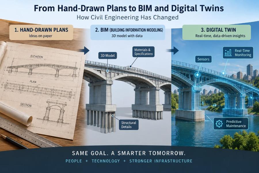
Hand sketches and paper drawings did not disappear because they were useless. They remain powerful ways to think, explain, review, and communicate. But digital tools have changed how teams coordinate, test alternatives, record decisions, and manage assets after construction.
For students, this shift affects the skills worth developing. For practicing engineers, it changes workflows, responsibilities, and risks. Understanding the path from drawings to Building Information Modeling (BIM) and digital twins helps separate useful technology from impressive-looking software.
✏️ The era of hand-drawn plans
For much of civil engineering history, design information was created manually. Engineers calculated loads, grades, quantities, and dimensions, then drafters converted decisions into plans, elevations, sections, schedules, and details.
A drawing set was both a design record and a construction instruction. Line weights, symbols, hatching, notes, and title blocks formed a precise visual language. Reading drawings well remains a core professional skill because drawings still communicate geometry, intent, tolerances, and contractual requirements.
📐 What paper drawings did exceptionally well
Paper drawings encourage deliberate thought. Producing a clear cross-section by hand forces the designer to decide where every component sits and how it relates to adjacent work.
They are also resilient. A printed plan can be reviewed on site without a login, battery, software version, or internet connection. For quick markups, field discussions, and formal record sets, a simple sheet still has real value.
- They provide a stable, readable snapshot of approved design intent.
- They make scale, proportion, and spatial relationships visible at a glance.
- They create a shared reference when digital access is limited.
🧮 The limits of a drawing-only workflow
The weakness of traditional documentation is not that drawings are inaccurate. The problem is that the same fact often has to be repeated in many places. A changed beam depth may affect a section, elevation, reinforcement detail, quantity takeoff, and specification note.
Each repeated item creates an opportunity for inconsistency. If one sheet changes while another does not, the construction team may receive conflicting instructions. Coordination relied heavily on experienced people noticing clashes through careful review.
🖥️ Computer-aided drafting changed production
Computer-aided design, commonly called CAD, moved linework from paper to digital files. This made copying, revising, layering, plotting, and distributing drawings faster than manual drafting.
CAD did not automatically create a smarter design process. Many early digital workflows simply reproduced the paper method on a screen: separate two-dimensional drawings, manually maintained notes, and independent files for each discipline. Still, digital drafting made iteration far more practical.
🗂️ Layers, standards, and digital discipline
CAD introduced a different kind of engineering discipline. Layers can distinguish proposed from existing work, utilities from structures, or dimensions from reference information. Blocks, styles, templates, and naming conventions help teams create consistent deliverables.
Without standards, however, a digital file can become harder to understand than a paper plan. A model or drawing is useful only when another person can identify its coordinate system, units, revision status, symbols, and intended purpose.
🌐 Surveying entered the digital workflow
Modern civil design depends on reliable spatial data. Total stations, global navigation satellite system receivers, laser scanning, aerial imagery, and geographic information systems have made it easier to capture and manage terrain, boundaries, utilities, and existing assets.
These tools do not eliminate survey judgment. A highly detailed point cloud can still be poorly located, incomplete, or unsuitable for a specific design decision. Engineers need to know the source, date, accuracy, datum, and limitations of the data they use.
🗺️ GIS added geographic context
Geographic information systems, or GIS, organize information by location. A municipality can combine parcels, drainage catchments, road conditions, land use, utility networks, and environmental constraints on mapped layers.
GIS is especially useful at planning scale. It can help identify where development may increase runoff, where a road corridor crosses sensitive areas, or which neighborhoods lie near aging water mains. It is not a substitute for detailed design geometry, but it connects engineering decisions to their wider setting.
🏗️ Civil design became more integrated
As projects grew more complex, isolated drawings became less adequate. A highway project may involve earthworks, pavements, bridges, drainage, traffic systems, utilities, environmental mitigation, and land acquisition. Each decision can affect several disciplines.
Digital tools made it easier to exchange information, but integration is primarily a management challenge. Teams need agreed responsibilities, timely reviews, and a clear process for resolving conflicts. Software can reveal a problem; people still decide what to do about it.
🧱 Understanding BIM beyond a 3D picture
Building Information Modeling, or BIM, is a process for creating and managing structured information about a built asset. The word “building” can be misleading: BIM approaches are used for stations, bridges, tunnels, treatment plants, roads, and other infrastructure as well.
A BIM model is more than a visual object. Elements may carry properties such as material, dimensions, identity, classification, specification references, installation status, or maintenance information. The model supports coordination, but it must be governed carefully to become trustworthy.
🔗 Objects carry relationships, not just lines
In a conventional drawing, a wall may be a pair of lines with notes. In an information model, it can be an object with a defined height, thickness, material, location, and relationship to slabs, openings, and finishes.
This distinction matters when changes occur. If a controlled model element changes, related views and schedules may update from the same source. The benefit is not automatic perfection; it is reduced duplication when the model is correctly built and checked.
📊 The dimensions of BIM information
People often describe BIM using additional “dimensions.” These labels are useful shorthand, but their meaning varies between organizations. They should not be treated as a universal maturity score.
| Common label | Typical meaning | Practical use |
|---|---|---|
| 3D | Coordinated spatial geometry | Visual review and clash identification |
| 4D | Model linked to programme activities | Construction sequencing and logistics planning |
| 5D | Model linked to quantities or cost information | Estimating and change assessment |
| 6D and beyond | Often used for sustainability, operations, or asset data | Lifecycle analysis and facilities management |
The key question is not which label a project claims. It is whether the information supports a defined decision at the right time.
🤝 Coordination is BIM’s everyday value
One of BIM’s most practical benefits is multidisciplinary coordination. Structural, architectural, mechanical, electrical, civil, and utility models can be reviewed together in a common coordinate system.
For example, a proposed stormwater pipe may pass through the space reserved for a foundation or cable tray. Finding that conflict in a coordinated review is generally less disruptive than finding it after excavation or installation. Not every “clash” is an error, though; reviewers must understand construction clearances, sequence, and design intent.
🔍 Clash detection needs engineering judgment
Automated clash tools can compare model objects and flag intersections or insufficient clearances. They are excellent at finding many possible issues quickly, especially in dense plant rooms, stations, and utility corridors.
But a report containing thousands of clashes is not a solution. Duplicate objects, temporary works, tolerated penetrations, and intentionally overlapping surfaces can create noise. Effective teams set rules, assign owners, prioritize risks, and record how each item was resolved.
📏 Model accuracy is not model usefulness
A model can look remarkably detailed and still be unsuitable for decision-making. Geometric detail, information completeness, survey reliability, and approval status are separate matters.
For instance, a preliminary bridge model may be useful for checking clearances and comparing options, even if reinforcement has not been designed. Pretending that early-stage geometry is construction-ready creates false confidence. Teams should define what each model is authorized to support.
🏷️ Level of detail and level of information
Model development is often described using terms such as level of detail and level of information. The first concerns how precisely an element is represented geometrically; the second concerns the properties and documents associated with it.
A pipe may be shown as a simple route at an early stage, then later receive its diameter, material, invert level, fittings, asset identifier, and inspection requirements. Adding every property too early wastes effort and makes models harder to maintain.
📦 The common data environment
A common data environment is the agreed system for sharing project information. It may include models, drawings, specifications, correspondence, surveys, issue logs, and approvals, with controlled access and revision history.
Its purpose is not merely storing files. It helps teams distinguish work in progress from shared information, published deliverables, and archived records. On a fast-moving project, knowing which version is current can prevent costly errors.
🔄 Version control protects design intent
When a design changes, the team must know what changed, why it changed, who approved it, and which downstream work is affected. Informal file copies with names such as “final_v7_revised” make this difficult.
Strong version control uses agreed naming, status codes, issue dates, and change records. The goal is traceability, not bureaucracy. A contractor should never have to guess whether a downloaded model supersedes the drawing already issued to the field.
🚧 BIM changes construction planning
Construction teams can use models to examine access routes, crane positions, excavation limits, material staging, temporary works, and sequence. Linking planned activities to model elements creates a four-dimensional view of how a site may evolve over time.
Consider a hypothetical constrained city-center project. A sequence model might show that installing façade panels before removing a tower crane would block later lifting operations. The visual simulation does not replace a method statement, but it can expose a logistical conflict early.
🧾 Quantities and cost still need verification
Models can support quantity takeoffs because objects have measurable geometry. This can speed comparisons between options and reveal how a design revision changes quantities.
However, automated quantities are only as reliable as the model’s rules. Openings may be omitted, classification may be inconsistent, temporary works may be excluded, and the estimating basis may differ from the modeling basis. Cost professionals must validate what the model includes before relying on its outputs.
🌱 Sustainability decisions can move earlier
Digital workflows can bring environmental questions into earlier design conversations. Designers can compare earthwork balances, material volumes, drainage options, energy demands, or embodied-carbon assumptions before the project is fixed.
These comparisons depend on assumptions and data quality. A model does not inherently make a design sustainable. It provides a structured way to test choices, document inputs, and revisit decisions as the design becomes more certain.
🏢 Infrastructure BIM is not identical to building BIM
Infrastructure projects deal with long corridors, terrain, geotechnical uncertainty, networks, and assets spread across large areas. A road model may need to represent alignments, profiles, corridors, surfaces, drainage networks, and earthwork volumes rather than rooms and floors.
Linear projects also depend heavily on survey control and chainage, the distance measured along an alignment. The useful information structure for a bridge, railway, water network, or flood channel should reflect how that asset is designed, built, inspected, and maintained.
🛰️ From BIM to a digital twin
A digital twin is commonly understood as a digital representation of a physical asset or system that is connected, to some degree, with real-world data and operational processes. The exact definition differs across organizations, so teams should state what their twin actually does.
A static as-built model is not automatically a digital twin. A twin may combine geometry, asset records, sensor readings, inspection findings, maintenance history, and performance models. Its value comes from supporting operational decisions, not from displaying a realistic 3D scene.
📡 Sensors give assets a live data stream
Sensors can monitor conditions such as water level, flow, vibration, displacement, temperature, strain, energy use, or equipment status. For a pump station, operational data may show whether a pump is running outside its expected range. For a bridge, monitoring may help identify changes worth investigating.
Sensor readings require context. A change in temperature may explain a structural movement that might otherwise look concerning. Conversely, a missing or drifting sensor can create misleading conclusions. Calibration, maintenance, and data validation are part of the engineering work.
🛠️ Asset management is the long-term opportunity
Civil assets often remain in service far longer than their design and construction phases. Owners need to know what they own, where it is, what condition it is in, what it costs to maintain, and which failures would have the greatest consequences.
A well-managed digital asset record can connect an individual valve, expansion joint, culvert, or retaining wall to inspections, manuals, drawings, and work orders. This can make maintenance planning more evidence-based, provided field updates are kept current.
⚠️ A digital twin cannot remove uncertainty
Physical infrastructure is influenced by weather, loading, deterioration, construction variability, ground conditions, and human operation. No model captures every variable, and no prediction should be presented as certainty when its assumptions are weak.
A useful twin makes uncertainty visible. It can show missing inspections, incomplete asset records, ranges of expected performance, or scenarios that require further investigation. Engineers must avoid treating dashboard colors as a replacement for inspection and professional judgment.
🔐 Data governance and cybersecurity matter
Connected infrastructure creates questions beyond geometry. Who owns the data? Who can edit asset records? How long are readings retained? What information should be shared with contractors, operators, or the public?
Systems connected to operational technology may also introduce cybersecurity risks. Access control, secure configuration, backups, and incident planning should be considered from the beginning. A highly connected asset with poorly managed access can create new vulnerabilities.
👷 Roles are changing, not disappearing
Automation can reduce repetitive drafting, checking, and data transfer tasks. It does not remove the need for engineers who understand loads, hydraulics, materials, construction methods, codes, risk, and public safety.
Instead, many roles are becoming more collaborative. Engineers increasingly work with surveyors, GIS specialists, model coordinators, planners, asset managers, software teams, and site personnel. The ability to explain engineering intent clearly across these groups is a major professional advantage.
🎓 Skills students should build now
Students do not need to master every platform before entering practice. They should build durable foundations: engineering mechanics, mathematics, materials, soil behavior, hydraulics, drawing interpretation, surveying principles, and technical communication.
Then add digital fluency with purpose. Learn how a model is structured, how coordinates are controlled, how quantities are checked, and how to question inputs. Useful habits include:
- Read drawings before relying on the 3D view.
- Check units, datums, assumptions, and revision status.
- Practice explaining a model issue in plain engineering language.
- Understand that attractive visualization is not proof of correctness.
🧠 The risk of software-driven design
Software can produce calculations, renderings, schedules, and models quickly. That speed can tempt users to accept outputs without understanding the underlying assumptions.
A drainage model may return a result even when catchment inputs are incomplete. A structural analysis may converge even when supports are modeled incorrectly. Digital competence includes knowing when to perform a reasonableness check with sketches, hand calculations, site knowledge, or an independent review.
🧩 Interoperability remains difficult
Projects rarely use one application from start to finish. Data moves among survey systems, design tools, analysis software, document platforms, scheduling tools, estimating databases, and asset-management systems.
Information can be lost or altered during exchange. Object classifications may not map cleanly, coordinates may shift, and geometry may simplify. Open data standards and well-tested exchange procedures can reduce these problems, but they do not eliminate the need to verify imports and exports.
💸 Technology has costs beyond licenses
Adopting BIM or a digital-twin approach requires training, templates, hardware, data storage, governance, integration, and ongoing maintenance. A small project may not benefit from the same level of modeling as a major rail program or treatment plant.
The sensible question is: which information will improve a real decision? A proportionate approach focuses effort where coordination risk, operational value, safety, or lifecycle cost justifies it.
✅ A practical implementation path
Organizations often struggle when they begin with software rather than a problem. A better approach starts by identifying recurring failures: drawing conflicts, missing field records, slow quantity updates, difficult handovers, or poor maintenance visibility.
- Define the decision or process to improve.
- Specify the required information, owner, format, and review point.
- Test the workflow on a manageable project or asset group.
- Measure whether it reduced rework, delay, uncertainty, or manual effort.
- Standardize what worked and improve what did not.
🧭 The core principle: better decisions, not more data
The journey from hand-drawn plans to BIM and digital twins is not a story of old methods becoming worthless. It is a story of civil engineering gaining new ways to connect design, construction, and operation.
Hand sketches still help engineers reason. Drawings still define and communicate work. Models can coordinate complex geometry and information. Digital twins can support operational awareness when reliable data and clear decisions are behind them.
The strongest workflow uses each tool for what it does best, while keeping accountability with informed people. Technology should make engineering intent clearer, risks more visible, and long-lived infrastructure easier to care for.
Civil engineering has changed most when information becomes more connected, but its purpose remains the same: make sound decisions that serve people safely over time. 🌉 🧭 💻