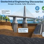
A building can look perfectly calm while the ground beneath it is slowly changing. A new embankment may settle for years after construction. Heavy rain can raise groundwater, soften a slope, and turn a manageable cut into a landslide risk. An earthquake can make loose, saturated sand behave less like solid ground and more like a fluid.
These are not merely construction-site problems. They affect homes, bridges, tunnels, retaining walls, railways, ports, dams, and the utility networks that connect communities. Much of civil engineering safety depends on understanding materials that cannot be manufactured to a uniform specification: soil and rock.
Geotechnical engineering developed through careful observation of failures, laboratory research, field measurements, and better models of ground behavior. Its major discoveries did not make foundations universally simple; they made engineers better able to ask the right questions before building.
The result is a discipline built around a practical truth: the ground is part of the structure. Understanding how that idea evolved explains why modern foundations and infrastructure are safer, more resilient, and more economical.
🌍 Geotechnical Engineering Begins with the Ground
Geotechnical engineering studies the engineering behavior of earth materials, especially soil, rock, and groundwater. It informs decisions about foundation depth, excavation support, slope geometry, retaining structures, earth dams, tunnels, and ground improvement.
Unlike steel or concrete, natural ground varies over short distances. A borehole may encounter dense sand, soft clay, fill, and weathered rock within one site. Designing safely therefore requires investigation, interpretation, and an explicit allowance for uncertainty.
🧱 Foundations Transfer Loads, Not Just Weight
A foundation transfers loads from a structure into the ground while limiting movement. Bearing capacity concerns whether the soil can support the load without shear failure; settlement concerns whether the structure moves too much even when it does not collapse.
A footing on dense sand may carry load largely through pressure spread beneath its base. A pile can transfer load through end bearing at depth, shaft resistance along its sides, or both. The discovery that load paths matter as much as nominal soil strength changed foundation design from rule-based sizing to mechanics-based analysis.
🔬 Soil Mechanics Made Ground Behavior Measurable
Early builders relied heavily on precedent: if a nearby structure stood successfully, its foundation arrangement might be copied. This approach was useful but unreliable when geology, loading, or groundwater differed.
The development of soil mechanics provided a language for measuring density, water content, grain size, strength, compressibility, and permeability. Instead of treating “earth” as one material, engineers could distinguish a free-draining gravel from a slowly consolidating clay and anticipate their very different responses.
💧 Effective Stress Explained Why Water Changes Everything
One of the most influential concepts in geotechnical engineering is effective stress. Soil grains carry load where they touch, but water in the pores between grains can carry part of the total pressure. The stress carried by the soil skeleton is the effective stress.
When pore-water pressure rises, effective stress falls. A sand deposit may lose shear strength during rapid loading; clay may soften; a slope may become less stable. Conversely, controlled drainage can increase effective stress and improve stability without changing the total weight of soil.
This concept explains why groundwater monitoring, drainage details, and construction sequence are often central safety measures rather than secondary site features.
🌧️ Pore Pressure Turned Seepage into a Design Issue
Water does not simply sit below ground level. It flows through connected pores, cracks, and drainage layers in response to differences in hydraulic head. That movement can create seepage forces, carry fine particles, and alter pressure distributions beneath structures.
Engineers now analyze likely seepage paths around dams, retaining walls, cofferdams, and deep excavations. Filters, drains, cutoffs, and relief wells are selected to control water safely. A drainage layer is only useful if it remains connected to an outlet and protected from clogging by migrating fines.
⏳ Consolidation Revealed Why Clay Settles Slowly
Soft saturated clay often settles over time after new loading. The process, called consolidation, occurs as excess pore water pressure dissipates and the soil skeleton gradually takes more of the applied load.
This discovery made it clear that a foundation can appear acceptable immediately after construction yet continue to settle over months or years. The rate depends on drainage distance and permeability, while the amount depends on compressibility, stress history, and loading.
For a highway embankment on soft clay, staged construction or temporary surcharge loading may be used to gain strength and induce settlement before the final pavement is placed.
📉 Settlement Became as Important as Ultimate Failure
A foundation need not collapse to cause severe damage. Differential settlement—uneven movement between parts of a structure—can crack masonry, distort doors, damage utility connections, and introduce unexpected forces into frames.
Modern design considers immediate settlement, consolidation settlement, and, in some soils, long-term creep. The tolerable movement depends on the structure. A flexible road embankment can accommodate movement that would be unacceptable for precision industrial equipment or a brittle historic wall.
🧭 Stress History Explained Overconsolidated Clay
Clay remembers previous loading. A deposit that once supported a thicker layer of soil, perhaps removed by erosion or excavation, may be overconsolidated. It can behave more stiffly under small reloading than a normally consolidated clay that has never carried higher stress.
This insight improved predictions of settlement and excavation response. It also introduced caution: sampling disturbance and laboratory interpretation can obscure stress history, so engineers combine test data with geological understanding and field observations.
🪨 Shear Strength Made Slope Analysis More Rational
Soil and rock slopes fail when driving forces exceed available resistance along a potential slip surface. Shear strength is often described through friction and cohesion-like components, though the appropriate model depends on material type, drainage conditions, and loading rate.
Instead of relying only on a visually “safe-looking” slope angle, engineers can examine likely failure surfaces, groundwater pressures, surcharge loads, and reinforcement. This brought more disciplined design to road cuts, open pits, embankments, levees, and natural hillside development.
🏔️ Landslide Lessons Emphasized Water and Geometry
Many slope failures involve a combination of steep geometry, weak or weathered material, rising water pressure, erosion at the toe, or added loading near the crest. Removing vegetation or changing drainage can also affect a previously stable hillside.
Useful countermeasures depend on the mechanism. Surface drains may reduce rainfall infiltration; horizontal drains can lower groundwater; buttresses support the toe; retaining systems provide resistance; regrading reduces driving forces. No single solution fits all slopes.
A common mistake is installing a retaining wall without resolving the water behind it. Water pressure and poor drainage can overwhelm an otherwise robust wall.
🧪 Laboratory Testing Connected Samples to Design
Laboratory tests made it possible to estimate engineering parameters under controlled conditions. Common tests assess grain-size distribution, plasticity, compaction response, shear strength, permeability, and compressibility.
Each test answers a limited question. A small specimen cannot capture every layer, fissure, or boulder in the field. Results must therefore be interpreted alongside borehole logs, groundwater data, in-situ testing, and the likely construction process.
🕳️ Site Investigation Reduced the Risk of Surprises
A geotechnical investigation usually combines desk study, site walkover, boreholes or trial pits, sampling, in-situ testing, and groundwater observations. Historical maps can identify former quarries, filled ground, old channels, or industrial uses that may affect ground conditions.
The goal is not to collect the maximum amount of data everywhere. It is to develop a reliable ground model: a reasoned description of stratigraphy, groundwater, variability, hazards, and parameters relevant to the proposed works.
📍 In-Situ Tests Measured Soil Where It Exists
Some important properties are difficult to preserve in a sample. In-situ methods test soil in place, reducing disturbance and providing continuous or frequent data with depth.
- Standard penetration testing provides an indication of resistance during borehole drilling.
- Cone penetration testing pushes an instrumented cone into soil and can provide detailed profiles in suitable ground.
- Pressuremeters and vane tests help characterize deformation or undrained strength in particular materials.
Correlations from these tests are valuable but not universal. Local geology, equipment procedure, and calibration affect how results should be used.
📡 Instrumentation Made the Ground Observable
Geotechnical behavior often develops during construction, when assumptions can be checked. Instruments such as piezometers, settlement plates, inclinometers, load cells, and survey targets measure pore pressure, movement, load, and deformation.
This led to the observational method: define expected behavior, monitor critical quantities, and prepare actions if readings approach unacceptable trends. It is not “build first and hope.” It requires a sound initial design, reliable monitoring, trigger levels, and authority to respond.
🚧 Excavation Support Advanced Beyond Simple Bracing
Deep excavations can cause ground movement outside the site boundary. That movement may affect neighboring foundations, buried utilities, rail lines, and roads even when the excavation itself remains stable.
Sheet piles, soldier-pile walls, diaphragm walls, secant pile walls, struts, anchors, and top-down construction offer different ways to retain ground. Selection depends on depth, water control, stiffness requirements, obstructions, property boundaries, and the tolerance of adjacent assets to movement.
🧰 Retaining Walls Became Systems, Not Isolated Structures
A retaining wall must resist earth pressure, sliding, overturning, bearing failure, and sometimes global slope instability. But successful performance also depends on drainage, backfill quality, compaction method, and the wall’s connection to nearby pavements or structures.
Mechanically stabilized earth walls were a major practical development. Reinforcement layers within compacted fill create a composite mass that can support steep faces. Their effectiveness relies on carefully controlled fill and durable reinforcement, not just an attractive facing panel.
🏗️ Deep Foundations Reached Better Bearing Strata
When shallow soils are weak, compressible, scour-prone, or vulnerable to seasonal movement, deep foundations can transfer load to more suitable ground. Piles and drilled shafts are widely used for bridges, waterfront structures, tall buildings, and heavily loaded industrial facilities.
They are not automatically safer or cheaper than shallow foundations. Installation can cause noise, vibration, ground displacement, spoil handling, or defects. Verification methods, including driving records, integrity testing, and load testing where appropriate, help confirm that installed elements perform as intended.
⚙️ Ground Improvement Expanded Viable Building Sites
Rather than always bypassing poor soil with deep foundations, engineers may improve the ground itself. Techniques include compaction, dynamic compaction, stone columns, deep soil mixing, grouting, prefabricated vertical drains, and reinforcement with geosynthetics.
The best method depends on soil type and the required outcome. Vibrocompaction suits certain granular soils but is not a cure for highly plastic clay. Deep mixing can create stiff soil-cement elements, but quality control of binder content and continuity is essential.
🧵 Geosynthetics Changed Earthwork Design
Geotextiles, geogrids, geomembranes, and geocomposites can separate materials, filter water, reinforce soil, provide drainage, or limit seepage. They made lighter, more adaptable solutions possible for roads on soft ground, reinforced slopes, landfill systems, and erosion control.
However, a geosynthetic is not a generic fabric layer. Its opening size, strength, stiffness, durability, installation damage resistance, and interface behavior must fit the application. Poor overlaps, wrinkles, ultraviolet exposure, or punctures can undermine performance.
🌊 Liquefaction Changed Earthquake Foundation Practice
During strong shaking, loose saturated sand can develop high excess pore-water pressure. Effective stress falls, and the deposit may lose much of its ability to resist shear. This phenomenon is called liquefaction.
Consequences can include settlement, lateral spreading toward free faces such as riverbanks, tilting of structures, and damage to buried pipelines. Assessment considers earthquake hazard, groundwater, soil density, stratigraphy, and the potential consequences of deformation—not merely whether a site contains sand.
🔧 Seismic Design Addressed Movement as Well as Strength
Seismic geotechnical design recognizes that foundations, slopes, retaining walls, and soil deposits interact with the structure above. Stiffness, damping, and potential ground deformation can change the demands placed on a bridge pier or building frame.
Possible responses include densifying loose ground, using stone columns or drains, selecting deeper foundation support, allowing for movement in utilities, and avoiding critical facilities on particularly hazardous ground where feasible. The suitable strategy is site-specific and depends on performance objectives.
🌊 Scour Research Protected Bridge Foundations
Flowing water can remove sediment around bridge piers, abutments, and coastal foundations. This localized erosion, known as scour, may expose or undermine foundations that were initially well embedded.
Design therefore considers channel behavior, flood flows, debris, bed material, and long-term changes in river alignment. Countermeasures such as rock armor, mattresses, collars, or deeper foundations require inspection because floods can displace protection or alter the channel in unexpected ways.
🏞️ Rock Mechanics Added Structure to “Solid Ground”
Rock may appear stronger and more predictable than soil, yet its engineering behavior is often governed by joints, bedding planes, faults, weathering, and groundwater. An intact laboratory core can be strong while a fractured rock mass is capable of sliding along discontinuities.
Rock mechanics improved tunnel support, dam abutment assessment, cut-slope design, and excavation planning by treating fractures as engineering features. Mapping their orientation and condition is often as important as measuring intact rock strength.
🚇 Tunnelling Learned to Control Ground Loss
Underground excavation changes stresses around a tunnel. If excessive soil is removed or allowed to flow into the opening, the ground surface may settle. In urban areas, even modest settlement can affect old masonry, utilities, or railway track.
Modern tunnel construction uses support systems, controlled face pressure where required, grouting, careful volume control, and monitoring. The key discovery is practical: tunnel safety depends not only on keeping the opening stable, but also on limiting how the surrounding ground deforms.
♻️ Climate and Groundwater Demand New Assumptions
Changing rainfall patterns, longer dry periods, sea-level rise, and more frequent extremes can affect geotechnical performance. Shrink-swell clays may move with seasonal moisture changes, coastal soils may face higher groundwater and erosion exposure, and intense storms can challenge drainage capacity.
Engineers cannot assign a universal adjustment to every project. They can, however, test whether design assumptions remain reasonable across plausible wet, dry, flood, and groundwater conditions, especially for long-lived infrastructure.
🏘️ Existing Infrastructure Requires Geotechnical Care
New work beside existing assets often creates the greatest risk. Dewatering can cause settlement beyond the excavation. Pile driving can transmit vibration. Utility trenches can alter drainage paths or remove support from nearby foundations.
A careful plan identifies sensitive neighbors, establishes condition surveys, controls construction methods, monitors movement, and defines response procedures. The safest foundation design can still perform poorly if construction effects on its surroundings are ignored.
📋 Codes Guide Design but Do Not Replace Judgment
Design standards provide common methods, load combinations, safety formats, and documentation expectations. They help engineers communicate assumptions and establish consistent minimum practice.
Yet codes cannot describe every geological setting or construction uncertainty. Good geotechnical design still requires professional judgment about the quality of data, the significance of variability, and whether a simplified model remains appropriate for the consequences of failure.
⚠️ Common Geotechnical Mistakes to Avoid
- Assuming one borehole represents an entire large or variable site.
- Treating groundwater observed on one day as a permanent water level.
- Using borrowed soil parameters without checking whether soil type and drainage conditions match.
- Ignoring construction sequence, temporary works, and dewatering effects.
- Specifying drainage without considering filter compatibility, maintenance, and discharge paths.
- Seeing monitoring as paperwork rather than a decision-making tool.
These mistakes are often linked by the same problem: treating ground as a fixed background instead of an uncertain material system responding to water, load, and time.
🧠 A Better Workflow for Safer Foundations
A strong geotechnical process starts early, before a foundation type is fixed. Early investigation can reveal whether a modest layout change, lower fill height, different bridge alignment, or relocated basement avoids a difficult ground condition.
- Develop a preliminary ground model from available information.
- Investigate the conditions that control the project’s main risks.
- Select foundation or improvement options that fit both ground and construction constraints.
- Check ultimate capacity, serviceability, groundwater, and temporary conditions.
- Set inspection, testing, and monitoring requirements for construction.
- Update the model when field evidence differs from expectations.
🤝 Collaboration Turns Data into Safer Decisions
Geotechnical engineers work most effectively when structural, hydraulic, environmental, construction, and asset-management teams exchange information early. A structural grid affects foundation loads; drainage changes pore pressures; a contractor’s equipment changes feasible pile types; maintenance teams need access to drains and instruments.
Safety improves when these decisions are coordinated rather than passed between disciplines as isolated requirements. The ground connects them all.
🔭 Digital Tools Improve Interpretation, Not Certainty
Three-dimensional ground models, geographic information systems, automated monitoring, remote sensing, and numerical analysis can reveal patterns that are difficult to see in separate drawings and spreadsheets. They are especially helpful on long corridors, complex excavations, and projects with large monitoring datasets.
But detailed graphics can create false confidence if the underlying investigation is sparse. A model remains an interpretation. Its value comes from transparent assumptions, sensible parameter ranges, and comparison with actual field behavior.
🛡️ The Core Lesson: Design with Ground, Water, and Time
The major discoveries in geotechnical engineering have a common theme. Soil strength depends on effective stress; water pressures change that stress; settlement can continue with time; and construction can alter all three. Foundations are therefore not selected from load alone.
Safer infrastructure comes from a defensible ground model, targeted investigation, appropriate analysis, constructible details, and monitoring where uncertainty or consequences justify it. The aim is not to eliminate every unknown, which is impossible in natural ground, but to identify the unknowns that matter and manage them deliberately.
The safest foundation is one designed for the actual ground conditions, changing water conditions, and real construction process—not an idealized version of the site. That principle continues to guide stronger, more resilient civil infrastructure. 🌉🪨💧