
A new warehouse is planned on a former riverside field. The architectural drawings are complete, structural loads are known, and the construction schedule is tight. Yet one question can still reshape the project: how will the ground actually respond when thousands of tonnes of load arrive?
Soil is not a manufactured material with one fixed strength value. It is a natural deposit shaped by water, stress history, weathering, construction activity, and sometimes decades of human alteration. Two boreholes only metres apart can encounter meaningfully different conditions.
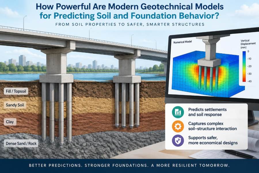
Modern geotechnical models give engineers far more powerful ways to interpret this complexity. They can estimate settlement, predict pore-water pressure changes, explore retaining-wall movements, and test foundation options before construction begins.
But a model is not a crystal ball. Its value depends on the ground investigation, the assumptions built into it, and the engineering judgement used to interpret the result. Understanding both its power and its limits is central to safe, economical foundation design.
🧱 What a Geotechnical Model Really Represents
A geotechnical model is a simplified representation of the ground and its interaction with a structure. It may be a hand calculation, a spreadsheet, a numerical finite-element model, or a three-dimensional digital ground model.
Every model converts a complicated site into selected layers, parameters, boundaries, loads, and rules describing material behaviour. That simplification is not a flaw by itself; it is how engineers make a problem solvable. The question is whether the simplification captures the mechanisms that matter for the design decision.
🗺️ The Ground Model Comes Before the Calculation
The most important model often begins as a conceptual ground model: a reasoned picture of the site’s geology, groundwater, landform, and expected hazards. It explains what deposits are present, how they relate to one another, and where uncertainty remains.
A numerical analysis cannot repair a weak conceptual model. For example, a highly refined simulation of uniform clay is misleading if a buried gravel channel, old excavation, or weak organic lens was omitted from the site interpretation.
Good practice moves from evidence to concept, then from concept to calculation. The order matters.
🔍 Why Soil Is Harder to Predict Than Steel
Steel members are produced to controlled specifications and tested under repeatable conditions. Soil is formed in place, and its properties vary with density, water content, stress history, particle arrangement, and loading direction.
Clay may behave stiffly under a small, short-term load yet compress substantially over years as water drains from its pores. Sand can be strong when dense and confined but lose stiffness when loosened by excavation or affected by cyclic loading.
Laboratory samples also have limits. Removing a sample from the ground changes its stress state, while very soft, fissured, gravelly, or sensitive materials can be difficult to sample representatively.
📚 The Evidence That Feeds the Model
Reliable prediction starts with multiple sources of site evidence. No single test provides a complete answer because each observes the ground at a different scale and under different conditions.
- Boreholes provide samples, logging information, and a view of layering with depth.
- In-situ tests, such as cone penetration or pressuremeter testing, measure response within the ground and can reveal variation between boreholes.
- Laboratory tests investigate strength, compressibility, permeability, and index properties under controlled loading paths.
- Geophysical surveys can help map broad changes but usually require calibration against direct ground data.
- Historical records and site walks may reveal fill, previous basements, drainage features, landslides, or industrial use.
The model should record not only interpreted values but also the quality and coverage of the evidence behind them.
💧 Groundwater Is an Active Part of the Problem
Groundwater is not merely a line drawn across a borehole log. Water pressure within the soil changes the effective stress carried by the soil skeleton, which strongly influences strength and deformation.
Excavation dewatering can lower water pressures and cause consolidation settlement beyond the excavation. Conversely, a rise in groundwater can reduce effective stress in certain soils, increase uplift pressure, or alter slope stability.
A single groundwater reading may reflect drilling disturbance, seasonal conditions, rainfall, or a perched water zone. Standpipes and piezometers observed over time often provide a better basis for design where water conditions are significant.
⚖️ Effective Stress Explains Much of Soil Behavior
Effective stress is the portion of total stress transmitted through contacts between soil particles. In simple terms, it is total stress minus pore-water pressure. Soil strength and stiffness are generally governed more directly by effective stress than by total stress alone.
Consider a saturated sand beneath a foundation. If load increases, particle contacts carry more force and the sand usually stiffens. If pore pressure rises while total load remains similar, the force at those contacts falls, and the soil may become weaker or deform more readily.
This principle allows engineers to connect drainage, consolidation, excavation, and foundation loading within one physical framework.
⏳ Drained and Undrained Responses Change the Answer
Whether water can flow out of a soil during loading determines its short-term response. In a permeable sand, drainage may occur quickly, so engineers often assess behaviour using drained parameters. In low-permeability clay, rapid loading may initially occur with little drainage, producing an undrained response.
This distinction is crucial for staged construction. An embankment placed quickly on soft clay may be stable at one rate of loading but unsafe at a faster rate, even if the final long-term condition appears acceptable.
Models must therefore use a loading timescale that matches reality, rather than treating every soil and construction stage as though drainage were instantaneous.
📉 Settlement Predictions Are Usually Ranges, Not Single Numbers
Foundation settlement may include immediate distortion during loading, consolidation as pore water dissipates, and longer-term creep in some soils. The relative importance of each component depends on soil type, stress history, foundation geometry, and drainage conditions.
A useful prediction distinguishes between total settlement and differential settlement. A building can often tolerate a relatively uniform downward movement better than a smaller difference in movement between columns or across a stiff wall.
Rather than treating a computed result as exact, engineers commonly evaluate plausible parameter ranges and identify what drives the upper and lower outcomes.
🏗️ Bearing Capacity Is Not the Same as Serviceability
Foundation design must address both ultimate and serviceability limit states. Ultimate limit states concern collapse mechanisms such as bearing failure, sliding, uplift, or overall instability. Serviceability limit states concern whether movements, rotations, vibrations, or cracking remain acceptable in use.
A pad footing may have adequate resistance against bearing failure yet settle enough to damage finishes, disrupt drainage falls, or overstress a sensitive façade. Conversely, a low settlement estimate does not remove the need to check strength.
Modern models are powerful partly because they can assess interacting mechanisms, but the design team must still ask the right performance question.
🧪 Constitutive Models Describe How Soil Changes
A constitutive model is the mathematical rule that relates stress, strain, stiffness, strength, and sometimes time or hydraulic behaviour. A simple model may assume a constant stiffness until failure. More advanced models allow stiffness to vary with stress level, unloading, reloading, or strain magnitude.
Advanced models can represent observed soil behaviour more realistically when supported by suitable data. They are especially useful where excavation sequences, stress relief, or small movements are important.
However, sophistication is not automatically accuracy. A complex constitutive model with poorly determined parameters can produce a more convincing-looking result without producing a more dependable one.
📐 From Hand Checks to Finite-Element Analysis
Hand calculations and established closed-form methods remain valuable. They are transparent, quick to review, and often well suited to routine foundations, slopes, and retaining structures.
Finite-element analysis divides soil and structural elements into many small zones and solves their interaction numerically. It can represent irregular geometry, construction staging, multiple soil layers, structural stiffness, seepage, and non-uniform loading.
The best workflow is frequently comparative rather than competitive: use simple methods to build intuition and check order of magnitude, then use numerical analysis where it adds decision-making value.
🧩 Meshes and Boundaries Can Quietly Control Results
In finite-element modelling, the mesh is the network of small elements used to approximate the domain. A mesh that is too coarse near a footing edge, retaining wall, or pile can miss concentrated deformation or stress gradients.
Model boundaries also matter. If they are placed too close to the structure, they can artificially restrain movement. If groundwater boundaries are unrealistic, predicted pore pressures and consolidation rates may be distorted.
Refining the mesh and moving boundaries farther away are simple sensitivity checks. When results change substantially, the original model setup needs review.
🏢 Soil–Structure Interaction Is a Two-Way Process
A structure does not simply apply a fixed load to passive soil. Structural stiffness redistributes load, while soil deformation changes how the structure responds. This is known as soil–structure interaction.
A flexible raft may follow differential ground movement differently from a rigid basement box. A framed building can transfer load from a settling column toward adjacent, stiffer supports. Pile caps, slabs, walls, and connections all influence this interaction.
Ignoring the structure’s stiffness can be unconservative in some cases and overly conservative in others. Collaboration between geotechnical and structural engineers is therefore more than a coordination exercise.
🪜 Foundation Type Changes the Mechanism
Shallow foundations spread load near the surface and are strongly influenced by near-surface variability, excavation disturbance, and compressible layers below the influence zone. Raft foundations distribute loads over a larger area and may reduce contact pressure, but they do not eliminate settlement.
Piles transfer load through shaft resistance, base resistance, or both. Their performance depends on installation method, soil layering, pile geometry, group effects, and how the superstructure shares load between piles.
A model should test the relevant mechanism for the selected foundation, not merely compare one calculated capacity value across alternatives.
🕳️ Pile Analysis Requires More Than an Ultimate Load
Pile foundations are often chosen because competent material lies below weak surface soils. Yet pile design still involves uncertainty: the strength profile may vary, pile installation can alter surrounding soil, and load–settlement behaviour may control long before ultimate resistance is approached.
For pile groups, stress bulbs from individual piles can overlap, mobilising settlement in deeper layers. Negative skin friction can also add axial load when surrounding soft soil settles relative to the pile.
Static load testing, integrity testing, and installation records can provide essential feedback. They do not replace interpretation, but they can reduce uncertainty at the point where design meets construction.
🧱 Retaining Walls Need Movement to Mobilise Resistance
Earth pressures behind a retaining wall depend partly on how much the wall moves. A wall that rotates or yields outward may mobilise lower active pressure than a rigid, heavily braced basement wall, which can remain closer to at-rest conditions.
Numerical models can simulate excavation stages, props, anchors, wall stiffness, and groundwater changes. This is particularly helpful in congested urban work where small wall movements may affect neighbouring foundations or utilities.
Using an earth-pressure condition without considering the wall’s likely movement and construction sequence is a common source of mismatch between calculation and site behaviour.
⛰️ Slopes Combine Geometry, Water, and Uncertainty
Slope stability models seek possible sliding mechanisms and compare resisting forces with driving forces. The critical surface may be shallow or deep, circular or non-circular, and influenced by weak seams, fill interfaces, weathered rock, or groundwater pressure.
Rainfall and poor drainage can change the problem without changing the slope’s visible geometry. Water pressure may rise in layers that are not obvious at the surface, reducing effective stress along a potential failure plane.
Because soil properties and water levels are uncertain, slope assessment benefits from scenarios: expected conditions, adverse seasonal conditions, and credible construction or drainage changes.
🌊 Seismic and Cyclic Loading Need Different Thinking
Repeated loading from earthquakes, waves, traffic, machinery, or wind can cause soil behaviour that a static model does not capture. In loose saturated sands, cyclic loading may generate excess pore pressure and reduce effective stress, creating liquefaction-related hazards in susceptible conditions.
Dynamic analyses require careful selection of input motion, damping assumptions, stiffness degradation, and boundary treatment. Their outputs can be highly sensitive to these choices.
For many projects, screening methods and code-based procedures are appropriate first steps. Detailed dynamic modelling is most useful when the site, structure, or consequences justify the added effort and specialist interpretation.
🖥️ Three-Dimensional Models Are Useful, Not Automatically Necessary
Three-dimensional analysis can represent corners, local excavations, non-symmetrical loading, tunnel crossings, pile-group geometry, and structures whose load path is not well represented in a two-dimensional section.
Yet 3D models require more input decisions, computational effort, checking, and interpretation. More dimensions also create more ways to hide an error in geometry, interfaces, staging, or parameter assignment.
A two-dimensional model may be more reliable for a long, uniform retaining wall. A 3D approach becomes more compelling when the omitted third-direction effects are likely to govern performance.
🧠 Machine Learning Can Recognise Patterns, With Guardrails
Machine-learning tools can assist with classification, interpolation, anomaly detection, and pattern recognition in large datasets from cone penetration tests, instrumentation, or ground investigation archives. They may help engineers identify relationships that deserve closer examination.
They are less reliable when asked to extrapolate beyond the conditions represented in their training data. Soil datasets are often incomplete, inconsistently labelled, and biased toward locations where projects were previously built.
Physical understanding remains essential. A machine-learning output should be treated as evidence to assess, not as an independent guarantee of ground behaviour.
📡 Monitoring Turns Prediction Into a Feedback Loop
Instrumentation can measure settlement, lateral wall movement, pore pressure, load, strain, and groundwater levels during construction. This creates an observational method approach: predict behaviour, define acceptable limits, monitor actual response, and adapt if observations approach trigger thresholds.
For example, a deep excavation model may predict a range of wall deflections. Inclinometers, survey targets, and piezometers can show whether the site is tracking within that anticipated range or behaving differently.
Monitoring only works when readings are timely, baselines are established, responsibilities are clear, and predefined actions follow unusual trends.
🚦 Trigger Levels Must Lead to Real Actions
A monitoring plan should not stop at collecting data. It needs alert and action levels that reflect the project’s risks, rate of movement, and available response time.
- An alert level may prompt increased reading frequency and design review.
- An action level may require changes to excavation sequence, dewatering, support installation, or loading.
- An emergency threshold may require stopping work and implementing a predefined safety response.
The exact values are project-specific. A threshold is useful only if it is connected to a realistic decision and communicated to those who can make it.
🔄 Back-Analysis Improves the Next Decision
Back-analysis compares measured field behaviour with model predictions and adjusts interpretation where justified. If a wall moves more than expected, possible explanations may include softer soil, higher water pressure, lower wall stiffness, installation effects, or an incomplete geological interpretation.
The goal is not to force the model to match every reading. Field data contain noise, instruments have limitations, and local behaviour may not represent the entire system. The goal is to improve the working understanding quickly enough to manage risk.
This learning loop is one reason geotechnical engineering continues through construction rather than ending when design drawings are issued.
🎯 Sensitivity Analysis Finds What Actually Matters
All models contain uncertain inputs. Sensitivity analysis changes selected parameters or assumptions within credible bounds and observes how the output responds. It identifies which uncertainties are worth reducing through additional investigation, testing, or monitoring.
If predicted settlement changes little across a plausible stiffness range, more elaborate stiffness testing may not change the decision. If a modest increase in pore pressure sharply reduces slope stability, groundwater monitoring and drainage design deserve priority.
This is a practical use of modelling power: not claiming certainty, but directing effort toward the uncertainties with the greatest consequence.
⚠️ False Precision Is a Serious Modelling Risk
A result reported to three decimal places can imply a confidence the data do not justify. Soil parameters are interpreted values, not universal constants, and construction conditions may differ from assumptions.
False precision can also arise from colourful contour plots and smooth deformation shapes. These graphics are useful for understanding mechanisms, but they should not distract from questions about input quality, calibration, and alternative scenarios.
A transparent approximate model is often safer than an opaque precise-looking model.
🧾 Model Verification and Independent Review Matter
Verification asks whether the model was implemented correctly: units, geometry, boundary conditions, mesh, drainage assumptions, load stages, and output extraction all need checking. Validation asks a harder question: does the model reasonably represent real ground behaviour for this application?
Independent review is particularly valuable for deep excavations, major earthworks, unusual foundations, or high-consequence assets. A reviewer can challenge the ground model and assumptions before construction makes errors expensive.
Simple hand checks remain an effective defence. If a detailed analysis disagrees sharply with physical expectation, that difference should be explained rather than ignored.
🧰 Choosing the Right Level of Model
The appropriate model is proportional to the decision and the risk. A lightly loaded small structure on well-characterised competent ground may need conventional calculations and sensible inspection. A major station excavation beside existing buildings may need staged numerical analysis, monitoring, and independent review.
| Project condition | Often useful approach | Key focus |
|---|---|---|
| Routine shallow foundation | Ground model, borehole data, conventional checks | Bearing resistance and settlement |
| Soft ground or variable fill | Parameter ranges and staged settlement assessment | Variability and construction sequence |
| Deep urban excavation | Numerical soil–structure interaction model plus monitoring | Wall movement, groundwater, adjacent assets |
| Complex pile-supported structure | Group-settlement assessment and field verification | Load sharing and installation effects |
The aim is not to use the most advanced available software. It is to use enough modelling, investigation, and observation to make a defensible decision.
👷 Construction Quality Can Override a Good Prediction
A foundation model assumes something about the completed works: founding level, excavation condition, concrete quality, pile installation, drainage, compaction, and load sequence. Poor execution can invalidate those assumptions.
Examples include founding a footing on softened formation, failing to remove unsuitable fill, uncontrolled dewatering, or changing a pile installation method without reassessing effects. Site inspection and clear hold points are part of geotechnical risk control.
Designers, contractors, and inspectors should treat unexpected ground as information to evaluate, not as an inconvenience to conceal.
🧭 A Practical Workflow for Better Predictions
Strong geotechnical predictions usually follow a disciplined sequence rather than beginning with software.
- Define the structure, performance requirements, construction sequence, and consequences of movement or failure.
- Develop and update a conceptual ground and groundwater model from available evidence.
- Plan investigation and testing to resolve the uncertainties that could change the design.
- Select analysis methods that capture the governing mechanisms without unnecessary complexity.
- Check parameters, assumptions, and results using independent calculations and engineering judgement.
- Specify observations, trigger actions, and review points for construction.
- Update the interpretation when new ground information or monitoring data become available.
This workflow makes the model part of a managed engineering process rather than a one-time report output.
🌉 The Core Principle: Powerful Models Need Ground Truth
Modern geotechnical models are remarkably capable. They can combine soil layering, groundwater flow, staged excavation, structural stiffness, time effects, and complex geometry in ways that were once impractical for routine design.
Their greatest strength is not the ability to produce a single definitive forecast. It is their ability to expose mechanisms, compare options, test sensitivity, communicate assumptions, and guide monitoring where uncertainty remains.
The strongest prediction combines an appropriate model with representative investigation, realistic construction assumptions, transparent checks, and observations from the site itself.
Modern geotechnical models are most powerful when they support engineering judgement rather than attempt to replace it. Used this way, they help engineers design foundations and earthworks that are safer, more efficient, and better prepared for the ground’s natural variability. 🌍🏗️🌉