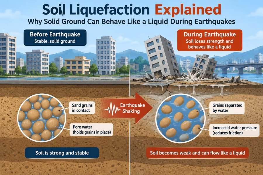

A road can look intact before an earthquake and be rippled, cracked, or partly submerged afterward. A building may remain standing yet settle unevenly into the ground. Buried pipes can rise toward the surface, while sand and water erupt through pavement like small fountains.
These are not necessarily signs that the soil “melted.” They can be consequences of soil liquefaction: a temporary and potentially severe loss of strength in certain saturated soils during strong shaking.
Liquefaction matters because every structure depends on its foundation soil. When that soil changes behavior in seconds, the loads, movements, and failure modes assumed during design can change with it.
For civil engineering students, the subject connects soil mechanics, earthquake engineering, foundations, infrastructure, and risk management. For practicing professionals, it is a reminder that ground conditions can control performance as much as the superstructure above.
🌍 What Soil Liquefaction Actually Means
Soil liquefaction is a process in which saturated, loose, granular soil loses much of its effective stress and shear strength during earthquake shaking. The soil-water mixture may then deform in a manner that resembles a viscous liquid.
The word resembles matters. Individual sand particles do not turn into water. Instead, water pressure between particles rises enough that particle-to-particle contact forces are greatly reduced.
Liquefaction is therefore a problem of stress transfer in soil. It is not simply a problem of wet ground.
🧱 Why Soil Normally Supports Foundations
Soil supports a footing, embankment, or pile through contact between its solid particles. Those contacts carry force and provide resistance to sliding, compression, and rotation.
In granular soils such as sand, the frictional resistance between particles is particularly important. Tighter packing and stronger particle contact generally provide greater resistance to deformation.
Water in the pores does not normally eliminate this support. The key question is how much of the total stress is carried by the grain skeleton rather than by the pore water.
⚖️ Effective Stress: The Key Soil Mechanics Idea
The principle of effective stress explains liquefaction. Total stress in soil is shared between the soil skeleton and the water in its voids. In simplified form, effective stress equals total stress minus pore-water pressure.
When pore-water pressure rises while total stress stays nearly the same, effective stress falls. As effective stress approaches zero, particle contacts lose their normal force and frictional strength can collapse.
This is why a deposit can appear firm under ordinary conditions but become unstable under cyclic earthquake loading.
💧 Saturation Creates the Necessary Setting
Classical earthquake-induced liquefaction requires soil voids to be substantially filled with water. In a dry sand deposit, there is no pore water to develop the pressure increase that drives this mechanism.
Saturation alone is not enough. Many saturated clay layers, dense sand deposits, and well-cemented soils do not liquefy in the same way as loose, susceptible granular deposits.
Still, a high groundwater table is a major warning sign. It places potentially susceptible layers closer to the condition needed for excess pore pressure to develop.
🏖️ Which Soils Are Most Susceptible
Loose to medium-dense sands and nonplastic silts are commonly associated with liquefaction susceptibility. These materials can tend to contract when shaken, particularly when they are young, loosely deposited, or poorly compacted.
Common settings include river floodplains, deltas, estuarine deposits, reclaimed land, hydraulic fills, beach deposits, and areas behind poorly controlled fills. Their history matters because deposition method and age affect density, fabric, and drainage.
Fine content alone does not settle the question. Some silty soils liquefy, while some soils with fines behave differently because plasticity, structure, and drainage characteristics alter their response.
🔍 Loose Sand Versus Dense Sand
Imagine two jars filled with saturated sand. One contains loosely placed particles; the other has been vibrated so the particles sit in a denser arrangement. Under shaking, the loose sand tends to seek a smaller volume.
Because the water cannot escape quickly during rapid loading, that tendency to contract increases pore-water pressure. Dense sand may instead tend to dilate, or expand slightly in volume, which can reduce or limit the pressure buildup.
Dense sand is not automatically immune, and loose sand is not automatically certain to liquefy. The distinction describes a tendency that must be evaluated with site-specific data and expected ground motion.
🔄 How Earthquake Shaking Builds Pore Pressure
Earthquakes impose repeated, rapidly reversing shear stresses on the ground. This is called cyclic loading. Each cycle can rearrange particles in a loose saturated deposit.
For a short time, water is trapped in the pores because drainage is too slow compared with the shaking. The particles try to contract, but the nearly incompressible water resists that volume reduction, so pore pressure rises.
Over enough strong cycles, the effective stress may become very small. The deposit can then undergo large strains, settlement, lateral movement, or loss of bearing support.
⏱️ Liquefaction Is Often a Brief but Critical State
The most severe loss of strength often occurs during and shortly after strong shaking. Once shaking stops, excess pore pressure can dissipate as water drains through the soil, allowing effective stress to recover.
Recovery is not the same as restoration. The ground may have densified, settled, cracked, spread laterally, or displaced structures while it was weak. A foundation does not necessarily return to its original position when strength comes back.
Drainage time depends on permeability, drainage path length, layering, and boundary conditions. Sandy deposits may dissipate pressure relatively quickly, whereas low-permeability layers can prolong deformation or settlement-related effects.
🌊 Flow Liquefaction and Cyclic Mobility
Engineers use related terms to describe different patterns of liquefaction-related behavior. The distinction helps communicate whether a deposit may undergo limited cyclic deformation or much larger post-shaking movement.
| Behavior | General description | Typical consequence |
|---|---|---|
| Flow liquefaction | Strength drops below the static shear stress needed for equilibrium. | Large, rapid movement on slopes or beneath embankments may occur. |
| Cyclic mobility | Repeated shaking produces strain and temporary softening, often with some retained strength. | Settlement, lateral spreading, and ground distortion may develop. |
Actual site behavior is more complex than a two-row classification. Soil layering, slope geometry, groundwater, and earthquake characteristics all influence the outcome.
🏗️ Bearing Capacity Loss Beneath Buildings
A shallow foundation relies on soil strength to resist shear failure and limit settlement. If liquefaction affects the supporting layer, the available bearing resistance can decrease sharply.
The building may settle, tilt, or translate laterally. Damage can range from serviceability problems, such as jammed doors and cracked finishes, to structural distress caused by differential settlement.
A uniform settlement is often less damaging than differential settlement. The latter bends frames, slabs, and utility connections because different parts of a structure move by different amounts.
↔️ Lateral Spreading on Gentle Slopes
Lateral spreading is the horizontal movement of gently sloping or free-face ground over a liquefied layer. It is often seen near riverbanks, waterfronts, channels, and the edges of reclaimed land.
The surface slope may be modest, but a liquefied layer can act as a weak zone beneath a relatively intact crust. Blocks of ground can crack and move toward the lower elevation or open water.
This mechanism is especially damaging to bridge abutments, retaining walls, buried pipelines, and pile-supported structures that must accommodate imposed ground displacement.
🏞️ Slope Failures and Embankment Instability
Earth embankments, levees, tailings facilities, and natural slopes may rely on a balance between driving forces and soil shear strength. Liquefaction can reduce that strength during shaking and upset the balance.
The resulting movement may be localized or extensive, depending on the geometry and continuity of susceptible material. Even a low embankment can be vulnerable if its foundation contains a loose saturated layer.
Assessment must consider both seismic loading and post-earthquake stability. A slope that survives the peak shaking may still have reduced resistance while excess pore pressure dissipates.
🫧 Sand Boils and Surface Ejecta
When high pore-water pressure finds a path upward, water and fine sand can emerge at the ground surface. These features are commonly called sand boils, sand blows, or ejecta.
They may appear as cones, vents, or patches of deposited sand. Their presence is useful evidence of excess pore pressure and upward seepage, but their absence does not prove that liquefaction did not occur below ground.
Surface crust thickness, pavement, drainage paths, and the location of susceptible layers all affect whether ejecta becomes visible.
🚰 Why Buried Pipes Can Float
Buried tanks, pipelines, and manholes can move upward when surrounding soil loses effective stress. Their buoyancy does not change, but the weakened soil provides much less downward restraint.
Joint separation, pipe breakage, and loss of grade may interrupt water, sewer, gas, and drainage systems exactly when they are needed for emergency response. Flexible joints and appropriate anchorage can help, but details must match expected movement.
Utility networks should be treated as systems. A robust pipe segment offers limited value if connections, valves, or crossings fail at vulnerable locations.
🌉 Bridges Face Ground Movement, Not Only Shaking
Bridge design often focuses visibly on columns, bearings, and deck response. Yet liquefaction can affect pile foundations, abutments, approach fills, and the soil supporting the entire system.
Lateral spreading can push against piles and abutments. Settlement of approach embankments can create a dangerous step between the road and bridge deck, while ground deformation can impose bending demands on deep foundations.
A bridge can have a sound superstructure and still become unusable if its approaches, supports, or surrounding ground are badly displaced.
🏙️ Ports, Waterfronts, and Reclaimed Ground
Waterfront infrastructure often combines loose granular fill, shallow groundwater, heavy structures, and an open-water edge that permits lateral deformation. This makes ports and reclaimed land prominent liquefaction-risk environments.
Quay walls may move outward, yard pavements may settle, cranes may lose level support, and utility corridors may distort. These effects can disrupt trade and emergency logistics even when individual buildings have limited visible damage.
Risk is not uniform across a reclaimed area. Fill placement methods, compaction records, seawall geometry, and variations in groundwater can produce sharp changes over short distances.
📜 Lessons From Past Earthquakes
Documented earthquakes in places such as Niigata, Japan; Christchurch, New Zealand; and coastal regions of California have shown the characteristic consequences of liquefaction: tilted buildings, settlement, lateral spreading, ejected sand, and damaged lifelines.
These events do not mean that every sandy waterfront will fail in the same way. They demonstrate a recurring engineering lesson: seismic hazard depends on the interaction of ground motion, soil profile, groundwater, topography, and infrastructure layout.
Post-earthquake observations are valuable because they improve mapping, field investigation methods, numerical models, and design practice. They must still be interpreted in their local geological context.
🗺️ The First Step: Understand the Site Model
A liquefaction assessment begins with a credible ground model. Engineers need to know what layers exist, how deep they are, where groundwater lies, how variable conditions are, and whether fills or old channels are present.
Desktop review is useful for identifying reclaimed land, historical waterways, prior site grading, and nearby evidence of liquefaction. It cannot replace subsurface investigation where a project’s consequences warrant direct data.
Groundwater should not be represented as one permanent number. Seasonal changes, tides, pumping, drainage failures, and perched water can alter the relevant condition.
🧪 Field Tests Used to Evaluate Susceptibility
Field testing estimates density, resistance, and stratigraphy in place. Common methods include the standard penetration test (SPT), cone penetration test (CPT), and shear-wave velocity measurements.
SPT provides a blow-count-based indication of penetration resistance, while CPT supplies a near-continuous profile of cone resistance, sleeve friction, and sometimes pore pressure response. Shear-wave velocity reflects small-strain stiffness and can complement other data.
No test should be treated as a magic answer. Results require corrections, quality control, geological judgment, and interpretation using procedures appropriate to the material and design framework.
🧫 Why Sampling Still Has a Role
Samples help identify grain size, fines characteristics, plasticity, organic content, and layering that a penetration profile may not fully reveal. Laboratory testing can also support a more detailed assessment of cyclic response.
Obtaining high-quality undisturbed samples from loose saturated sand is difficult. Disturbance during sampling can alter density and structure, so laboratory results must be weighed alongside in-situ measurements.
For soils with significant fines, classification and plasticity testing become especially relevant. Calling every fine-grained layer “clay” or every silty layer “sand” can lead to poor screening decisions.
📈 Comparing Earthquake Demand With Soil Resistance
Many practical methods compare the cyclic demand expected from an earthquake with the cyclic resistance inferred from field data. This produces a screening-style measure of whether triggering is plausible at a given depth.
Engineers also account for factors such as earthquake magnitude, peak ground acceleration, overburden stress, groundwater, fines behavior, and depth-dependent stress conditions. Modern assessments may use probabilistic seismic hazard inputs and more advanced effective-stress analyses where warranted.
A triggering calculation is not the complete design. It must be followed by evaluation of settlement, lateral spreading, foundation response, and consequences for the proposed structure.
📏 Triggering Is Not the Same as Damage
One frequent mistake is stopping at the question, “Will the layer liquefy?” A thin liquefiable seam deep below a lightly loaded structure may have a very different implication from a thick, shallow liquefiable layer beneath a bridge abutment.
Engineering decisions depend on deformation and performance. Relevant questions include how much settlement may occur, whether the site can spread laterally, how foundations will interact with moving soil, and what level of disruption is acceptable.
Conversely, a calculated susceptibility does not automatically require expensive remediation. The structural system, site geometry, project importance, and feasible alternatives all belong in the decision.
🛠️ Densification as a Ground Improvement Strategy
Where loose granular soil is accessible, densification can reduce liquefaction susceptibility by increasing particle contact and decreasing contractive behavior. Methods may include vibrocompaction, dynamic compaction, and compaction grouting.
Method selection depends on depth, soil gradation, groundwater, nearby structures, vibration tolerance, and the area requiring treatment. A technique effective in clean sand may be less effective in silty soil.
Verification is essential. Post-treatment CPT, SPT, or other measurements should demonstrate that the improvement achieved the design intent rather than merely documenting that equipment was used.
💦 Drainage and Pore-Pressure Relief
Drainage-based measures seek to give water a faster escape path during cyclic loading, limiting excess pore-pressure buildup. Stone columns, gravel drains, and prefabricated drainage systems are examples used in suitable ground conditions.
Drainage solutions can be attractive where large-scale densification is impractical, but their performance depends on installation quality, filter compatibility, drainage continuity, and the permeability of surrounding soils.
They are not a universal substitute for understanding deformation. A project may still need to address lateral loads, settlements, or weak layers that remain after pressure relief is considered.
🪨 Reinforcement, Replacement, and Mixing
Other options include excavating and replacing poor soil, installing stone columns, constructing soil-cement columns, or using deep soil mixing to create stronger composite ground. These methods can improve strength, stiffness, drainage, or all three.
Reinforcement may be targeted beneath foundations, embankments, or retaining structures instead of treating an entire site. Targeted treatment can be economical, but transition zones require careful detailing because differential movement may concentrate there.
The best solution is rarely selected from a catalog alone. Construction access, spoil disposal, environmental constraints, adjacent assets, and quality assurance can be as decisive as theoretical performance.
🏛️ Foundation Strategies When Soil Cannot Be Treated
Deep foundations can transfer structural load through weak or liquefiable layers to more competent material below. However, piles do not simply bypass all liquefaction consequences.
Moving ground can impose kinematic loads on piles, and loss of lateral support in liquefied layers can increase bending demands. Group effects, downdrag from settling soil, pile-head restraint, and abutment movement must all be considered.
Raft foundations, stiffened mats, and structural ties may improve tolerance to differential settlement in some projects. These approaches manage deformation; they do not necessarily eliminate the underlying geotechnical hazard.
🚧 Construction Practices That Prevent New Problems
Construction can alter liquefaction risk. Uncontrolled fill placement may create loose saturated zones, while excavation dewatering or changed drainage can affect groundwater conditions beyond the immediate work area.
Specifications should address lift thickness, moisture conditioning, compaction testing, material quality, and recordkeeping. For critical fills, proof of density alone may not capture all relevant features, especially if segregation or variable fines are present.
Temporary works deserve attention too. A trench, excavation, or temporary embankment may be vulnerable during a seismic event even if the final permanent design is robust.
⚠️ Common Misconceptions to Avoid
- “All wet soil liquefies.” Saturation is necessary for classical liquefaction, but density, gradation, plasticity, stress history, and shaking all matter.
- “Bedrock means no liquefaction risk.” A site can have shallow bedrock and still contain susceptible overburden or fill that affects foundations and utilities.
- “Deep piles solve everything.” Piles can be loaded by laterally spreading or settling ground and require seismic soil-structure interaction design.
- “A hazard map is a site investigation.” Maps support screening and planning; they do not define the detailed soil profile beneath a specific project.
- “No sand boils means no liquefaction.” Surface evidence may be absent despite damaging subsurface strength loss or settlement.
🧭 Risk Communication and Performance Objectives
Liquefaction discussions should describe consequences in practical terms: expected settlement range, possible lateral displacement, utility vulnerability, repair time, and acceptable post-earthquake function. Saying a site is simply “safe” or “unsafe” hides the decisions that matter.
Different projects have different performance objectives. A warehouse, a hospital, a port fuel line, and an emergency bridge may justify different levels of investigation, mitigation, and redundancy.
Uncertainty should be communicated plainly. Subsurface conditions are inherently variable, and earthquake motions are uncertain; sound engineering manages those uncertainties through investigation, conservative detailing, verification, and contingency planning.
🧠 The Core Principle: Keep the Soil Skeleton Working
Liquefaction becomes understandable once effective stress is clear. Earthquake shaking can cause loose, saturated soil to contract; trapped water pressure rises; grain contacts lose force; and the ground loses the frictional skeleton that normally carries load.
The consequences depend on context. On level ground, settlement may dominate. Near a riverbank or waterfront, lateral spreading may control. Beneath critical infrastructure, deformation compatibility can matter as much as whether triggering occurs.
Strong liquefaction engineering combines a reliable site model, appropriate testing, demand-resistance evaluation, deformation assessment, and mitigation tailored to project performance goals.
Solid ground is only as dependable as the particle contacts and drainage conditions that allow it to carry effective stress during shaking. Recognizing that principle turns liquefaction from a surprising disaster image into a problem that engineers can investigate, design for, and reduce. 🌍🏗️💧