
A new road may look like a ribbon of asphalt, a bridge like a simple span, and a building like a finished stack of floors. Before any of those forms can exist, someone must establish exactly where they belong: on the correct parcel, at the correct elevation, and at the correct angle.
That task is construction surveying. A small positioning error at the start of a project can become an expensive problem when foundations are poured, steel is erected, or drainage no longer falls in the intended direction.
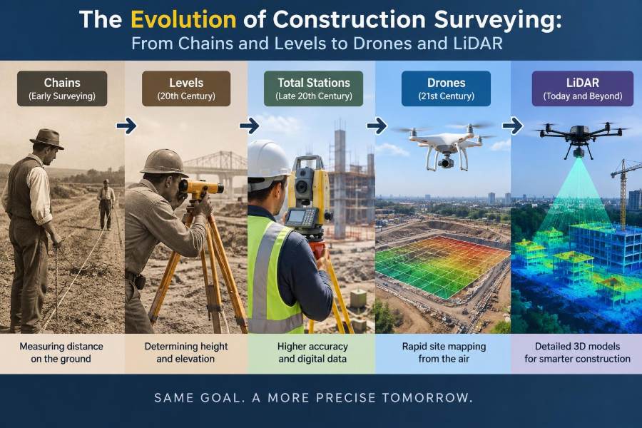
Surveyors once crossed sites with chains, tapes, levels, notebooks, and carefully placed stakes. Modern crews may now collect millions of measured points from a drone flight or a laser scanner while checking coordinates through satellite-based equipment.
The tools have changed dramatically, but the central responsibility has not: translate a design into reliable positions on the ground, then verify that construction matches the intended geometry.
🧭 What Construction Surveying Actually Does
Construction surveying is the measurement and layout work that supports a project from early site investigation through final as-built records. It connects drawings and digital models to physical locations, elevations, lines, grades, and dimensions.
Typical tasks include setting out building corners, establishing road centerlines, checking excavation depth, locating utilities, monitoring structural movement, and documenting what was built. The work is not merely “taking measurements”; it is a controlled process for making decisions with spatial data.
📐 Why Position and Elevation Control Matter
Every structure has geometric requirements. A retaining wall needs the right alignment and footing level. A pipe needs a continuous grade so water or wastewater flows as designed. Bridge bearings must sit in locations that allow the superstructure to fit.
Horizontal position answers where something is located on a plan. Elevation answers how high or low it is relative to an approved reference. Construction failures can arise when either is wrong, even if materials and workmanship are otherwise sound.
⛓️ The Era of Chains and Tapes
Early field measurement relied heavily on physical distance measurement. Survey chains, and later steel tapes, were stretched between points to establish lengths. A chain was divided into standard links, allowing surveyors to record distances in repeatable units.
This method demanded discipline. Sag, temperature change, slope, poor alignment, and inconsistent tension could all affect a measured distance. Crews used procedures such as keeping the chain horizontal or applying corrections when the required precision justified them.
Although electronic tools replaced chains for most modern layout, the underlying lesson remains useful: a distance is meaningful only when the measurement method, reference points, and conditions are understood.
🔭 Levels, Staffs, and the Rise of Reliable Heights
Spirit leveling transformed the ability to transfer elevations across a site. A level instrument creates a horizontal line of sight, while a graduated staff held at known and unknown points lets the surveyor calculate differences in height.
The method is still valued because careful differential leveling can provide highly dependable elevation control. On projects where vertical tolerance is tight, a digital level or optical level may remain the preferred check even when GNSS equipment is available.
🧱 The Benchmark: A Site’s Vertical Anchor
A benchmark is a stable point with a known elevation. It gives the project a common vertical reference, allowing multiple crews and construction stages to work from the same datum.
Good benchmarks are protected, clearly documented, and checked rather than assumed correct forever. A temporary mark on a curb, loose stake, or vulnerable wall may be convenient, but it can be disturbed by equipment, settlement, or later site work.
- Permanent benchmarks are intended to remain stable over long periods.
- Temporary benchmarks support day-to-day construction control.
- Check points independently test whether the control still agrees with expectations.
📏 The Theodolite and Precise Angles
The theodolite made it possible to measure horizontal and vertical angles with much greater control than simple sighting methods. By combining angles with measured distances, surveyors could establish coordinates and set out complex alignments.
For a road curve, for example, an angle-based method allows points to be placed along the designed path rather than relying on visual judgment. Theodolites also supported traverse surveys, in which connected lines and angles build a controlled network across a site.
🔺 Triangulation and Survey Control Networks
Triangulation uses measured angles within triangles to determine positions. If one side and enough angles are known, other distances and point locations can be calculated. This principle helped surveyors extend control over large areas before satellite positioning.
Modern construction control networks may use different instruments, but they follow the same logic: establish a set of well-defined points, observe them carefully, and use them as the framework for all subsequent layout and verification.
🗺️ From Field Books to Coordinated Plans
Traditional survey field books recorded observations, sketches, station descriptions, and calculations by hand. A good sketch often explained site conditions that a column of numbers could not: a fence line, a curb, a tree, or the side of a structure where a mark was placed.
Digital collection has reduced manual transcription, but documentation remains essential. A coordinate without a clear datum, point description, date, and method may be difficult—or unsafe—to reuse later.
⚙️ Electronic Distance Measurement Changes Fieldwork
Electronic distance measurement, commonly called EDM, uses electromagnetic signals to determine distance between an instrument and a reflector or target. It made distance measurement faster and generally more repeatable than pulling tapes over uneven ground.
EDM also enabled crews to work efficiently across obstacles such as ditches, traffic lanes, or rough terrain. However, it did not remove the need for careful setup: instrument height, reflector height, atmospheric conditions, and target identification still influence the final result.
🎯 Total Stations Combine Angles and Distance
A total station combines an electronic theodolite with EDM. Once the instrument is oriented to known control points, it can measure angles and distances and compute point coordinates in the field.
This made construction layout more direct. A crew can load design coordinates, guide a prism holder to the desired position, and mark the point when the displayed offset reaches the project tolerance. The instrument can also collect as-built points for comparison with the design.
🤖 Robotic Total Stations and One-Person Layout
Robotic total stations can automatically track a prism, allowing one operator to control the instrument remotely while moving around the site. This can speed repetitive layout on building floors, industrial facilities, and other settings with clear lines of sight.
The productivity gain is real, but it depends on conditions. Tracking can be interrupted by equipment, workers, reflective surfaces, dust, or obstructions. A robotic workflow still requires a competent person to verify control, select the correct point, and recognize an implausible result.
🛰️ GNSS Brings Satellite Positioning to the Site
Global Navigation Satellite System, or GNSS, is the general term for satellite constellations used for positioning. Receivers estimate their position by processing signals from satellites, often with correction methods that improve accuracy for surveying work.
GNSS is especially useful for open sites, earthworks, route surveys, and machine control. It can provide a position without a direct line of sight between the surveyor and a total station, which changes how rapidly a crew can cover large areas.
📡 RTK Corrections and Their Limits
Real-time kinematic, or RTK, positioning uses corrections from a known base station or network service to improve GNSS results in real time. It is widely used for construction staking, topographic work, and equipment guidance.
RTK is not magic. Buildings, trees, terrain, cranes, and reflective surfaces can block or distort satellite signals. Multipath occurs when a signal reaches the receiver after reflecting from a surface, potentially producing a misleading position.
A sensible workflow checks the reported solution status, observes a known point, and changes methods when site conditions are poor. A total station or level may be the stronger choice near tall structures or beneath dense cover.
🌍 Datums: The Reference System Behind Every Coordinate
A coordinate only has meaning within its reference system. A horizontal datum defines how positions relate to the Earth, while a vertical datum defines the reference for elevations. Projects may also use a local grid designed to simplify work across a specific site.
Mixing coordinate systems can shift an entire layout even when every individual observation is precise. Before mobilizing, teams need agreement on coordinate units, grid versus ground distances, datum, geoid model where relevant, and the approved control information.
📦 CAD Models Become Field Layout Data
Computer-aided design files and building information models can supply points, lines, surfaces, and alignments directly to survey instruments. This reduces repeated manual entry and makes it easier to compare the constructed work with the intended geometry.
Yet a model is not automatically field-ready. Layers may contain outdated objects, assumed coordinates, or elements intended only for visual presentation. Survey staff must confirm which design version is authorized and whether the model’s origin, units, and coordinate system match the site control.
🏗️ Machine Control Reshapes Earthmoving
Machine-control systems use GNSS, total stations, sensors, and digital terrain models to guide excavators, dozers, graders, and other equipment. The operator can see the planned surface and the machine’s position relative to it.
For broad earthworks, this can reduce repeated staking and help operators achieve designed grades more consistently. Surveyors still have a central role: they establish control, prepare or validate the surface model, check the finished work, and investigate discrepancies.
🚁 Drones Extend the Surveyor’s View
Unmanned aircraft systems, commonly called drones, can capture overlapping aerial images across a site. Photogrammetry software identifies common features in those images to create orthomosaic maps, three-dimensional models, and point clouds.
A drone is particularly useful for stockpiles, inaccessible slopes, progress documentation, and early site mapping. Instead of walking every part of a large open area, the survey team can capture extensive visual and spatial coverage from above.
📷 Photogrammetry Depends on Image Geometry
Photogrammetry is not simply aerial photography. Its accuracy comes from known camera geometry, sufficient image overlap, stable processing, and well-distributed ground control or independent check points when the required accuracy calls for them.
Vegetation, water, uniform surfaces, shadows, and moving equipment can complicate reconstruction. A photogrammetric surface may represent the top of grass, brush, vehicles, or stored materials rather than the bare earth needed for a grading calculation.
🔦 LiDAR Measures With Laser Pulses
LiDAR, short for light detection and ranging, emits laser pulses and measures their return to calculate distances. Mounted on terrestrial scanners, drones, vehicles, or aircraft, it can rapidly create dense point clouds of surfaces and objects.
Unlike image-based mapping, LiDAR does not depend on visible texture in the same way. It can perform well in low-light conditions, though its result still depends on sensor quality, flight or scan planning, surface reflectivity, calibration, and processing choices.
☁️ Understanding the Point Cloud
A point cloud is a large collection of measured points in three-dimensional space. Each point may include coordinates and attributes such as intensity or color. Viewed together, the points describe a road corridor, building façade, excavation, or industrial plant.
Dense data does not guarantee accurate data. A cloud can look impressively detailed while containing alignment errors, gaps, noise, or an incorrect reference system. Quality assessment must consider both completeness and positional reliability.
🌿 Ground Classification Is Not Automatic Truth
LiDAR processing often classifies points into ground, vegetation, buildings, and other categories. A ground model is then created from points considered to represent the terrain. This is valuable for corridors and heavily vegetated sites, but classification is an interpretation by software and operator settings.
Low branches, retaining walls, steep banks, and construction debris can confuse automated routines. Survey teams should inspect critical zones and use field checks before relying on a derived surface for excavation quantities or drainage design.
🏢 Terrestrial Laser Scanning for Complex Structures
Terrestrial laser scanners collect dense point clouds from fixed positions on the ground. They are well suited to façades, tunnels, mechanical rooms, bridges, historic structures, and complicated existing conditions.
Multiple scans must be registered, or aligned, into one coordinate system. Targets, overlapping geometry, and control points can support this process. If registration is weak, separate scans may fit visually while carrying unacceptable positional drift.
✅ Accuracy, Precision, and Tolerance Are Different
Accuracy describes closeness to the accepted true or reference value. Precision describes repeatability: whether repeated observations closely agree with each other. A system can be precise but inaccurate if a systematic error shifts every result.
Tolerance is the permitted deviation for a construction element. The required survey method should be selected from the tolerance and risk, not from whichever technology appears most advanced.
| Situation | Primary concern | Often suitable approach |
|---|---|---|
| Fine structural layout | Tight local position and elevation | Total station with verified control; leveling for critical heights |
| Open earthworks | Fast coverage and grade control | GNSS, machine control, and independent checks |
| Existing complex structure | Dense three-dimensional capture | Terrestrial scanning, supported by survey control |
| Large-area progress mapping | Efficient surface and imagery collection | Drone photogrammetry or aerial LiDAR, with appropriate validation |
🧪 Quality Control Starts Before Measurements
Reliable survey results begin with planning. The team should review the design, identify tolerances, establish control, choose an appropriate instrument, and define independent checks before layout starts.
Good quality control also includes routine instrument checks. For example, level collimation, total-station compensator behavior, prism constants, and GNSS setup details should not be treated as background assumptions when the work is critical.
🔁 Independent Checks Catch Expensive Errors
A strong field practice is to verify important work through a different observation, setup, or method. A building grid laid out from one instrument station can be checked from another station. An RTK point can be compared with known control. A critical elevation can be rechecked by leveling.
Repeating the same mistaken setup is not truly independent. The value of a check comes from its ability to expose a wrong backsight, incorrect control coordinate, transposed digit, or misunderstood drawing.
⚠️ Common Construction Surveying Mistakes
Many failures are procedural rather than technological. Sophisticated equipment can calculate quickly, but it cannot determine whether the operator selected the wrong design revision or occupied the wrong control point.
- Using disturbed control marks without re-verification.
- Confusing local site coordinates with a projected grid coordinate system.
- Applying the wrong prism constant or instrument height.
- Staking from an unapproved or superseded drawing.
- Accepting GNSS positions in obstructed conditions without a check.
- Assuming a drone-derived surface represents bare ground beneath vegetation.
- Failing to preserve clear as-built records of changes made in the field.
🦺 Safety Is Part of the Measurement Plan
Surveyors often work near traffic, excavations, cranes, heavy equipment, water, and energized facilities. The fastest route to a point is not automatically the safe route to a point.
Drone operations add separate considerations, including airspace rules, site authorization, weather, battery management, and keeping people clear of takeoff and landing areas. Technology should reduce exposure where possible, but it does not remove the need for task-specific safety planning.
👷 The Surveyor’s Role Is Evolving, Not Disappearing
Automation has changed routine tasks, especially high-volume data collection and repetitive layout. It has also increased the importance of judgment: validating control, understanding uncertainty, managing data, and explaining whether a result is suitable for the decision being made.
Modern survey professionals increasingly work across field measurement, model coordination, geospatial data management, machine guidance, and quality assurance. The profession’s value lies less in operating a single instrument than in delivering defensible spatial information.
🎓 Skills Worth Building for Students and Professionals
Students entering construction surveying benefit from learning both fundamental geometry and current digital workflows. A person who understands leveling, traverses, errors, and coordinate systems is better able to diagnose a problem when software output seems questionable.
- Practice reading plans, sections, profiles, and site-control notes.
- Learn the difference between a coordinate system, datum, projection, and local grid.
- Develop careful field-note and file-management habits.
- Use total stations, GNSS, levels, and scanning tools where training access allows.
- Ask what tolerance the construction decision actually requires.
- Learn to communicate limitations clearly to engineers, contractors, and clients.
🔮 What Comes Next: Connected Data and Smarter Workflows
Construction surveying is moving toward more connected workflows, where design models, field observations, machine-control data, and as-built records can be exchanged with fewer manual handoffs. Cloud platforms and automated comparison tools can make deviations easier to identify while work is still underway.
These systems also create new risks around version control, data ownership, cybersecurity, and overconfidence in automated alerts. A highlighted deviation still needs interpretation: it may indicate an installation error, a coordinate mismatch, a model issue, or a sensor problem.
🌉 The Core Principle Across Every Generation
From a chain stretched across a field to a LiDAR sensor collecting millions of points, construction surveying has always been about controlled relationships: point to point, design to ground, and observation to reference.
The best method is not always the newest one. It is the method that can safely deliver the required accuracy, coverage, speed, and documentation under actual site conditions—and that includes enough checking to make the result trustworthy.
Construction surveying evolves through technology, but it succeeds through sound control, verified measurements, and informed professional judgment. When those principles guide the work, chains, levels, total stations, drones, and LiDAR all become parts of the same essential engineering discipline. 🌉🛰️📐