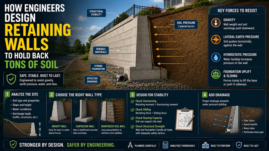

Retaining walls may look like simple barriers made of concrete, stone, steel, or masonry, but structurally they perform a demanding job: holding back large masses of soil that naturally want to move sideways and downward. 🏗️🌍
A retaining wall might support a highway cut into a hillside, create a flat building site on sloping ground, protect a basement, stabilize an excavation, or hold landscaping soil at different elevations. In each case, the wall must resist forces created by soil weight, groundwater, nearby vehicles, buildings, and sometimes earthquakes.
The challenge is not merely making the wall strong enough. Engineers must also make sure the entire system does not slide, overturn, sink, crack excessively, or fail because of trapped water.
That is why retaining wall design combines soil mechanics, structural engineering, drainage, geology, and construction planning. A successful wall works together with the soil around it rather than simply acting as a massive barrier.
🌍 Why Soil Pushes Against a Retaining Wall
Soil may appear solid, but it behaves differently from concrete or steel.
A mass of soil is made of particles that can move relative to one another. Gravity continuously pulls those particles downward.
If a slope is steep enough, the soil naturally tends to spread outward and slide.
When engineers build a retaining wall in front of that soil, the wall prevents the soil from moving freely.
The soil therefore pushes horizontally against the wall.
This sideways force is called lateral earth pressure.
The deeper the soil, the greater the pressure generally becomes.
Near the top of the wall, pressure may be relatively small.
Near the bottom, the wall must resist much larger forces.
A simplified pressure diagram often looks triangular:
Ground Surface
│
│  >
│  >>>
│  >>>>>
│  >>>>>>>
│  >>>>>>>>>>
└──────────────
Increasing soil pressure with depth
This increasing pressure is one of the most important ideas in retaining wall design. 📐
⚖️ Engineers Consider Different Earth Pressure Conditions
Soil pressure depends partly on whether the wall is allowed to move.
Geotechnical engineers commonly consider three conditions:
🟢 Active Earth Pressure
If the wall moves slightly away from the soil, the soil can relax and expand.
The horizontal pressure decreases to what is called the active earth pressure.
Many free-standing retaining walls are designed using this condition.
🔴 Passive Earth Pressure
If the wall pushes into the soil, the soil becomes compressed.
The soil can develop much greater resistance.
This is called passive earth pressure.
Passive resistance can help stabilize foundations and embedded wall portions.
🟡 At-Rest Earth Pressure
If the wall cannot move enough for the soil to expand or compress significantly, the pressure remains at an intermediate condition known as at-rest pressure.
Basement walls connected rigidly to floors and building structures may experience at-rest earth pressure.
Choosing the correct pressure condition is essential because it directly affects the calculated wall forces.
🧮 How Engineers Estimate Soil Pressure
A simplified expression for lateral soil pressure is:
Horizontal pressure = earth pressure coefficient × vertical soil pressure
The vertical soil pressure increases with depth because of the weight of the soil above.
In simplified form:
σᵥ = γz
where:
- σᵥ = vertical stress,
- γ = unit weight of soil,
- z = depth.
The horizontal pressure may then be estimated as:
σₕ = Kγz
where K is an earth pressure coefficient.
The value of K depends on factors such as:
- soil friction angle,
- wall movement,
- wall geometry,
- backfill slope,
- soil-wall friction.
Classical methods such as Rankine theory and Coulomb theory are commonly used to estimate these pressures. 📊
For real projects, engineers may also use numerical modeling or more advanced geotechnical analysis.
🏋️ Why the Resulting Force Acts Near the Bottom
Because lateral earth pressure generally increases with depth, the total force is not applied at the wall’s midpoint.
For a simple triangular pressure distribution, the resultant force acts approximately one-third of the wall height above the base.
This matters because the soil force creates an overturning moment.
A tall wall can therefore experience a very large rotational demand around its toe.
Engineers must design the wall so its resisting weight and foundation forces are sufficient to counteract this tendency.
🔄 Three Major Failure Modes: Sliding, Overturning, and Bearing
A retaining wall can fail in several ways.
Three of the most important are:
➡️ Sliding
The soil pushes horizontally against the wall.
If the horizontal force becomes greater than the resistance at the base, the entire wall can slide forward.
Sliding resistance can come from:
- friction under the foundation,
- passive resistance in front of the wall,
- shear keys,
- anchoring systems.
Engineers calculate a factor of safety against sliding to make sure there is sufficient resistance.
🔃 Overturning
The lateral soil force tries to rotate the wall forward.
The wall’s weight, soil above the footing, and foundation reactions help resist this overturning moment.
If the overturning effect becomes too large, the wall may rotate around its front edge.
⬇️ Bearing Failure
The wall transfers loads into the soil beneath its footing.
If those pressures exceed the soil’s bearing capacity, the foundation can sink or rotate.
Engineers therefore calculate the pressure distribution under the base and compare it with allowable soil bearing pressures.
🧱 The Basic Anatomy of a Cantilever Retaining Wall
One of the most common reinforced concrete retaining walls is the cantilever wall.
It typically consists of:
- a vertical stem,
- a horizontal base slab,
- a heel beneath the retained soil,
- a toe extending in front of the wall.
A simplified cross-section looks like:
        Retained Soil
        █████████████
        █████████████
        █████████████
        │
        │ Stem
        │
────────┴────────────
   Heel      Toe
The stem behaves somewhat like a vertical cantilever beam fixed at the base.
The base slab distributes the loads into the soil below.
Interestingly, the soil resting above the heel adds downward weight, helping stabilize the wall against overturning.
🦶 Why the Heel and Toe Matter
The heel is the part of the footing extending behind the wall beneath the retained soil.
The toe extends in front of the wall.
Their dimensions strongly influence stability.
A larger heel can increase stabilizing weight because more soil rests above it.
A larger toe can help spread foundation pressure.
However, making the base wider increases excavation, concrete volume, and cost.
The engineer therefore chooses a geometry that achieves acceptable stability without unnecessary material.
🔩 Reinforcement Controls Bending and Cracking
Concrete is strong in compression but weak in tension.
The lateral soil pressure bends the retaining wall stem.
This creates tensile stresses that must be resisted by steel reinforcement.
Engineers therefore place reinforcing bars where tension is expected.
For a typical cantilever retaining wall, significant reinforcement is often concentrated near the soil-facing side of the stem.
The base slab also requires reinforcement because the heel and toe bend under different upward and downward pressures.
Structural calculations determine:
- bar size,
- bar spacing,
- development length,
- concrete thickness,
- crack-control reinforcement.
Proper detailing is just as important as overall stability. 🔩🧱
💧 Water Can Be More Dangerous Than Soil
One of the most serious retaining wall problems is water pressure.
If rainwater or groundwater collects behind a wall, hydrostatic pressure can build up.
Water weighs roughly 9.81 kN per cubic meter, so a deep water column can create substantial lateral force.
Unlike well-drained soil, water pressure increases directly with depth.
A wall designed only for dry soil pressure may be overloaded if drainage fails.
This is why retaining wall engineers often say that drainage is part of the structure. 💧⚠️
🚰 How Drainage Protects Retaining Walls
Several drainage measures can be used behind a wall.
🪨 Free-Draining Gravel
A layer of coarse gravel or crushed stone allows water to move downward rather than becoming trapped behind the wall.
🧵 Geotextile Fabric
Geotextiles can separate the drainage aggregate from surrounding fine soil.
This helps prevent small particles from clogging the drainage zone.
🚿 Perforated Drain Pipe
A perforated pipe near the base collects water and carries it away to a safe discharge point.
🕳️ Weep Holes
Some retaining walls include small openings through the wall.
These allow water to escape.
Good drainage can dramatically reduce the loads applied to the structure.
🚗 Surcharge Loads Add Extra Pressure
Retaining walls often support more than soil.
Additional loads near the top of the wall are called surcharges.
Examples include:
- parked vehicles,
- highway traffic,
- storage areas,
- buildings,
- construction equipment,
- stockpiled materials.
A heavy truck near the edge of a retaining wall increases stress in the soil and therefore increases lateral pressure on the wall. 🚛
Engineers model these surcharge effects so the wall is not designed only for the weight of the backfill itself.
🏢 Nearby Buildings Can Influence Wall Design
If a building foundation is located close to a retaining wall, the load from the building can increase stresses in the retained soil.
The wall may need to support not only the soil mass but part of the building-induced pressure.
This is particularly important for:
- basement excavations,
- urban construction,
- property-line retaining walls,
- underground parking structures.
Geotechnical analysis helps determine how those loads spread through the soil.
🌋 Earthquakes Can Increase Lateral Forces
In seismic regions, retaining walls may experience additional loads during earthquakes.
Ground acceleration can increase lateral earth pressure and cause movement of the retained soil.
Engineers may use seismic earth pressure methods such as Mononobe–Okabe analysis for certain wall types and conditions.
Seismic design may consider:
- increased earth pressure,
- wall inertia,
- soil liquefaction risk,
- permanent displacement,
- drainage performance.
For critical infrastructure, sophisticated numerical models may be used to study soil-structure interaction during earthquakes. 🌍⚡
🪨 Soil Type Changes Everything
Not all soil behaves the same way.
A retaining wall supporting dense gravel may experience very different behavior from one supporting soft clay.
Important soil properties include:
- unit weight,
- friction angle,
- cohesion,
- permeability,
- compressibility,
- groundwater conditions.
Granular soils such as sand and gravel often drain relatively well.
Clay soils may retain water and develop different pressure behavior.
Engineers rely on geotechnical investigations to determine these properties rather than simply assuming typical values.
🔬 Why Site Investigation Is Important
Before designing a major retaining wall, geotechnical engineers may investigate the site using:
- boreholes,
- test pits,
- soil sampling,
- laboratory tests,
- groundwater measurements,
- penetration tests.
These investigations help answer questions such as:
- How strong is the foundation soil?
- Is groundwater present?
- Are there weak soil layers?
- Could the site settle?
- Is the backfill likely to drain?
- Is the slope naturally stable?
A retaining wall designed using incorrect soil assumptions can fail even if its concrete and steel are perfectly constructed.
🏔️ Engineers Must Check Global Slope Stability
Sometimes the retaining wall itself may be stable, yet the entire hillside can still fail.
Imagine a perfectly strong wall located at the bottom of a large unstable slope.
A deep sliding surface could pass underneath the wall and through the surrounding ground.
In that situation, the wall may move together with the failed soil mass.
This is called a global stability problem.
Engineers therefore evaluate potential slip surfaces through the soil behind and beneath the wall, particularly for high walls and steep slopes. ⛰️
🧱 Gravity Retaining Walls
A gravity retaining wall relies mainly on its own weight to resist soil pressure.
These walls may be constructed from:
- mass concrete,
- stone masonry,
- large concrete blocks,
- gabions.
They are usually thick and heavy.
Because their stability depends on weight, gravity walls often require more material than reinforced cantilever walls.
However, they can be simple, durable, and effective for lower heights. 🪨
🧺 Gabion Retaining Walls
Gabions are wire baskets filled with rock.
They form heavy, flexible retaining structures.
Gabion walls have several advantages:
- good drainage,
- tolerance for some settlement,
- relatively simple construction,
- natural appearance.
Because water can flow through the rock-filled structure, hydrostatic pressure is less likely to accumulate.
Gabions are often used along roads, rivers, slopes, and erosion-prone areas. 🌿
🧩 Segmental Retaining Walls
Many landscaping and highway walls are built using interlocking concrete blocks.
These are called segmental retaining walls.
For taller walls, layers of geogrid are often extended backward into the soil.
The geogrid reinforces the soil mass itself.
Instead of relying only on a heavy wall at the front, the system creates a large block of reinforced soil that acts together.
This type of system is known as mechanically stabilized earth, or MSE.
🛣️ Mechanically Stabilized Earth Walls
MSE walls are widely used in transportation infrastructure.
They usually consist of:
- facing panels or blocks,
- compacted backfill,
- horizontal reinforcement layers.
The reinforcement may be made from:
- steel strips,
- steel grids,
- geosynthetic materials.
Friction between the reinforcement and soil helps prevent the soil mass from pulling outward.
MSE walls can support highways, bridge approaches, and large embankments efficiently. 🚧
⚓ Anchored Retaining Walls
Some retaining walls are too tall or too heavily loaded to rely only on their base.
Engineers may use ground anchors or tiebacks.
These anchors extend through the wall into stable soil or rock behind the active failure zone.
They are tensioned to pull the wall backward.
Anchored walls are often used for:
- deep excavations,
- urban basements,
- highway cuts,
- temporary construction support.
The anchors reduce bending in the wall and can allow much taller excavations with relatively slender wall sections. ⚓
🏙️ Sheet Pile and Soldier Pile Walls
Deep excavations may use steel or concrete elements driven or installed vertically into the ground.
🔩 Sheet Pile Walls
Interlocking steel sheets create a continuous barrier.
They are commonly used near water and in excavations.
🏗️ Soldier Pile Walls
Vertical steel beams are installed at intervals.
Horizontal lagging spans between them to retain soil.
These systems can be supported with internal braces or external anchors.
They are particularly valuable where there is limited room for a wide concrete footing.
📏 Settlement Must Be Controlled
Retaining walls are not perfectly rigid.
The foundation soil can compress under load.
If one part of the wall settles more than another, cracks or misalignment may develop.
Engineers therefore evaluate:
- total settlement,
- differential settlement,
- soil stiffness,
- foundation preparation.
Drainage pipes and utilities passing through or near the wall may also be vulnerable to movement.
🧱 Backfill Compaction Is Critical
Even a well-designed retaining wall can develop problems if the soil behind it is placed poorly.
Backfill is usually placed in layers and compacted.
Proper compaction provides predictable soil strength and reduces future settlement.
However, heavy compaction equipment operated too close to the wall can temporarily create large lateral pressures.
Construction procedures therefore specify:
- backfill material,
- layer thickness,
- moisture content,
- compaction level,
- equipment limitations near the wall.
Construction quality has a major influence on long-term performance. 🚜
🌡️ Temperature and Shrinkage Can Cause Cracking
Long concrete retaining walls expand and contract with temperature.
Concrete also shrinks as it cures and loses moisture.
Engineers may provide:
- construction joints,
- contraction joints,
- expansion joints,
- temperature reinforcement.
These details help control where cracks form and how wide they become.
A wall can be structurally stable yet still experience durability problems if cracking is not controlled properly.
🧪 Durability Matters Over Decades
Retaining walls are expected to survive years of exposure to:
- rain,
- groundwater,
- salts,
- freezing and thawing,
- temperature changes,
- soil chemicals.
Engineers may specify:
- adequate concrete cover,
- durable concrete mixtures,
- corrosion-resistant reinforcement,
- waterproofing membranes,
- protective coatings.
For highway walls exposed to deicing salts, corrosion protection can be particularly important.
🧮 Factors of Safety Provide Engineering Margin
Real-world soil conditions are uncertain.
Material properties vary.
Loads change.
Construction is never mathematically perfect.
Engineers therefore do not design retaining walls exactly at the theoretical failure point.
They use factors of safety.
For example, the available resistance to sliding should exceed the predicted sliding force by an acceptable margin.
Similar checks are made for:
- overturning,
- bearing capacity,
- structural strength,
- global stability.
The required values depend on codes, design methods, and project conditions.
🖥️ Modern Engineers Use Computer Models
Simple retaining walls can often be analyzed using hand calculations and classical earth pressure theory.
Complex walls may require specialized software.
Computer models can evaluate:
- nonlinear soil behavior,
- staged excavation,
- anchor forces,
- groundwater flow,
- seismic effects,
- wall deformation.
Finite element methods can represent both the soil and structure, helping engineers understand how loads transfer between them.
However, software does not replace engineering judgment.
The results are only as reliable as the soil properties, assumptions, and boundary conditions used in the model. 💻
🔍 Warning Signs of Retaining Wall Problems
Existing walls should be inspected when signs of distress appear.
Potential warning signs include:
- wall leaning,
- large cracks,
- bulging,
- soil movement,
- blocked drainage outlets,
- water leaking through cracks,
- settlement at the top,
- separation between wall sections.
Small cosmetic cracks may not necessarily indicate serious failure, but significant movement should be evaluated by qualified professionals.
Retaining wall failure can release large quantities of soil suddenly, making major distress a safety concern. ⚠️
🧠 Why Retaining Wall Design Is Really About Managing Forces
The wall itself is only one part of the system.
Engineers are managing a balance among several forces:
Soil pushes sideways.
Wall weight pushes downward.
Foundation soil pushes upward.
Base friction resists sliding.
Drainage removes water pressure.
Reinforcement resists bending.
Anchors or geogrids can provide additional restraint.
A successful design keeps all of these effects in equilibrium with adequate safety margins. ⚖️
🏗️ Holding Back Tons of Soil Safely
A retaining wall may support thousands of tons of soil, yet its basic engineering principle is understandable: the wall and surrounding ground must provide enough resistance to balance every force trying to move the retained soil.
Engineers begin by studying the soil and groundwater. They calculate lateral earth pressure, include surcharge loads, and determine how those forces act on the wall. They then check whether the structure could slide, overturn, sink, bend excessively, or become unstable as part of a larger slope.
Concrete thickness and reinforcement provide structural strength. 🧱
The foundation distributes loads into the ground.
The heel and wall weight provide stability.
Drainage systems prevent dangerous water pressure.
Anchors, geogrids, piles, or other reinforcement may be added when loads become larger.
The result is a structure that can quietly resist enormous forces for decades.
The central principle can be summarized simply:
A retaining wall holds back soil not by relying on concrete alone, but by carefully balancing earth pressure with structural strength, foundation resistance, wall weight, reinforcement, and drainage. 🏗️🌍💧
That combination of soil mechanics and structural engineering is what allows roads to cross hillsides, buildings to sit on sloping sites, basements to remain stable underground, and enormous masses of earth to stay safely in place.