
A sudden downpour can turn an ordinary street into a moving map of water. Gutters fill, puddles spread across low spots, and water races toward a storm drain—or, when drainage is overwhelmed, toward a doorway, garage, or basement.
It is easy to think stormwater simply “finds a way.” In reality, its path is shaped by small changes in level, surface texture, soil condition, obstacles, and drainage structures. A curb a few centimetres high or a shallow depression can completely redirect flow.
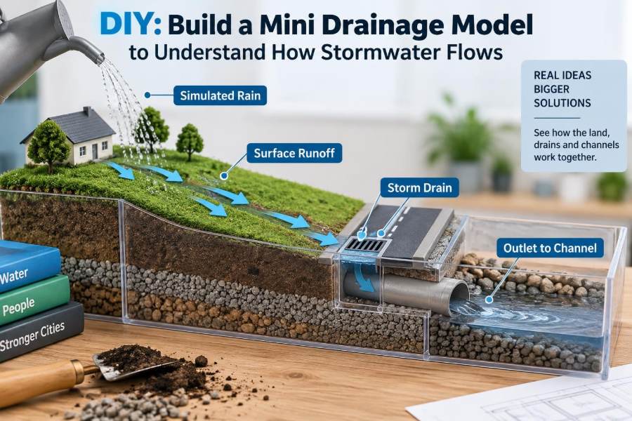
A mini drainage model makes those relationships visible. With a tray, soil or sand, simple household materials, and a controlled amount of water, you can observe the same basic processes civil engineers consider when planning sites, roads, channels, and stormwater systems.
This is not a scaled design tool for a real property. It is a hands-on demonstration of hydraulic behaviour: how runoff begins, where it concentrates, why erosion develops, and how drainage measures work together.
🌦️ What This Mini Model Can Teach
The model represents a small catchment: an area of land that drains to one common outlet. Rain falls on the catchment, some water infiltrates into the ground, and the remaining water becomes surface runoff.
By changing one feature at a time, you can see cause and effect directly. Steepen a slope and flow speeds up. Add an impermeable “roof” and more water reaches the low point. Block an outlet and ponding develops upstream.
These are simplified observations, but they build useful engineering intuition. Real drainage design adds measured rainfall, topographic survey data, pipe capacity, soil testing, local rules, and safety factors.
🧠 The Core Idea: Water Moves Downhill
Gravity drives drainage. Water moves from a location with higher hydraulic head—its elevation and water level—to a location with lower hydraulic head.
In an open model, elevation is usually the clearest influence. A shallow swale, or gently sloped vegetated channel, may carry water more reliably than a visually dramatic ditch if it provides a continuous downward path.
Water does not need a steep slope to flow. It needs a connected gradient. A nearly level area can drain slowly, while one tiny reverse slope can trap water and create persistent ponding.
🧰 Gather Safe, Simple Materials
Choose materials that let you reshape the ground quickly and observe water clearly. A shallow plastic storage lid, baking tray reserved for non-food use, or sturdy tray makes a practical base.
- Shallow tray with a raised edge
- Sand, garden soil, potting mix, or a mix of sand and soil
- Small stones, twigs, sponge pieces, and modelling clay
- Cardboard, plastic sheet, or foil for roofs and paved surfaces
- A cup, small jug, or spray bottle for controlled “rainfall”
- Food colouring or washable paint for clearer flow paths
- Ruler, spoon, and towel for setup and cleanup
Keep electrical items away from the activity, protect indoor surfaces, and avoid pouring sediment-laden water into a sink unless you first let solids settle and dispose of them appropriately.
📦 Choose a Tray That Reveals the Landscape
A transparent tray can help you see infiltration and wetting near the sides, while an opaque tray often gives better visual contrast on the surface. The tray must be large enough to include an uphill area, a low area, and an outlet path.
Its rim also matters. It acts like the boundary of your miniature site. If water overtops that rim, you have created a model version of runoff leaving the intended drainage area or of flooding beyond a containment edge.
Place the tray on a stable, protected table. You may later raise one side slightly with a book to create a broad overall slope, but begin on a level surface so your landform controls the flow.
🏔️ Shape a Small Catchment
Spread your soil mix across the tray and form a modest high point near one end. Grade the surface gradually toward the opposite end, leaving room for a shallow channel and a collection point.
A useful layout has three zones: an upper slope where rain lands, a middle area where runoff begins to concentrate, and a lower outlet zone. Avoid making a single smooth ramp; real sites contain local high spots, shallow depressions, and transitions.
Press the surface lightly rather than compacting it hard. Excessive compaction can make the model behave like pavement, which may be useful later but hides the difference between permeable and impermeable ground.
📐 Create a Continuous Drainage Path
Use the back of a spoon or a finger to form a narrow, shallow channel from the upper area to the lower edge. This channel represents a swale, gutter, ditch, or small open drain.
The important feature is continuity. Check it by looking across the model from the side. A local hump in the channel can create a miniature blockage, causing water to spread sideways instead of continuing toward the outlet.
Keep the channel shallow at first. An oversized, sharply cut trench can dominate the experiment so completely that you no longer observe how sheet flow gathers naturally from the surrounding surface.
🚪 Build an Outlet and Collection Point
At the low end, form a small basin or use a cup positioned just outside the tray to collect outflow. If the tray has no safe way to discharge, allow water to collect in a clearly defined low area instead.
An outlet is the point where water leaves a catchment or enters the next part of a drainage system. In a real system, that may be a storm inlet, culvert, channel, pipe, detention basin, or natural watercourse.
Never interpret a model outlet as proof that a full-scale outlet is adequate. Real drainage capacity depends on dimensions, slope, roughness, debris, pipe losses, downstream water levels, and design storm conditions.
🌧️ Make Repeatable Model Rainfall
For useful comparisons, apply water in a repeatable way. Fill the same cup to the same mark and pour it from roughly the same height and location for each test.
A spray bottle better represents dispersed rainfall, while a small jug can represent a concentrated burst. Neither perfectly duplicates natural rainfall, but consistency lets you compare different terrain and surface conditions.
Begin gently. Watch where water first darkens the soil, where it infiltrates, and where a thin layer of water begins to travel over the surface. Then repeat with a faster application rate.
💧 Separate Infiltration From Runoff
Infiltration is water entering the soil surface. Runoff is water moving over the ground when rainfall exceeds the ground’s ability to absorb, store, or transmit water.
At the beginning of a test, dry soil may absorb much of the water. As the soil becomes wetter, its available storage decreases and surface flow often develops more quickly. This is why a later storm can produce different runoff than an earlier storm of similar intensity.
In your model, note the delay between pouring water and seeing flow at the outlet. That delay is a simple indicator of how storage, infiltration, and travel time influence a catchment response.
🟤 Compare Different Soil Conditions
Run the same rainfall test on loose sand, ordinary soil, and firmly pressed soil. Keep the model’s general slope similar as you compare the results.
Sand commonly allows water to enter quickly, although its behaviour depends on how it is packed and whether it is already wet. Fine or compacted soil may form surface runoff sooner, especially when water is applied rapidly.
Real soil is more complicated than a tray sample. Layers, roots, cracks, groundwater, organic matter, and prior moisture all affect infiltration. The experiment illustrates a principle, not a site investigation.
🏠 Add an Impervious Surface
Lay a small piece of plastic, foil, or coated cardboard on the upper slope to represent a roof, driveway, or parking area. Ensure its lower edge directs water toward the channel.
An impervious surface resists infiltration. Water landing on it is rapidly converted to runoff and often discharged in a concentrated stream at an edge, downspout, or curb line.
Observe how a small hard surface changes the rest of the model. It may increase flow in one channel while reducing wetting in nearby soil. This is one reason development changes local drainage patterns even when the total land area remains the same.
🛣️ Test a Road, Curb, and Gutter
Form a smooth, gently sloped strip with cardboard or clay to represent a road. Add a thin clay ridge along one side as a curb, and shape a narrow depression beside it as a gutter.
Curbs are not merely edges. They guide shallow flow parallel to a road until water reaches an inlet or low point. If the gutter has a hump, water can cross the road or pond against the curb.
This test shows why pavement grading is precise work. A road that looks level to the eye can still require carefully planned crossfall and longitudinal slope to move water safely.
🕳️ Simulate a Storm Drain Inlet
Place a small opening, perforated bottle cap, or short tube at the low point of the gutter to represent an inlet. Position a container below or beyond it to collect water if your setup allows.
Water only enters an inlet when it can reach the opening. If the inlet sits above the surrounding gutter, sediment builds in front of it, or flow bypasses it because of local grading, the inlet captures less water than expected.
Try partly covering the opening with small leaves or bits of sponge. This is a demonstration of debris vulnerability, not a recommendation to obstruct real drainage infrastructure.
🍂 See How Debris Creates Ponding
A few twigs, soil clumps, or leaf fragments in a narrow channel can slow water, redirect it, and raise the water level upstream. As ponding grows, water may find a new route around the obstruction.
In a full-scale system, debris management is part of drainage performance. A channel or inlet that has enough theoretical capacity may still function poorly when its entrance is blocked.
Do not assume every obstruction is harmful. Vegetation and roughness can intentionally slow water in bioswales and other green infrastructure. The question is whether the feature is placed and maintained to support the intended flow path.
🏞️ Watch Sheet Flow Become Concentrated Flow
Early in a gentle test, water may move as a thin, broad film called sheet flow. As it encounters small hollows and surface irregularities, it converges into tiny rills—small channels cut by runoff.
Concentrated flow has more erosive potential than evenly distributed sheet flow because more water and energy are focused in a smaller area. In the tray, this appears as narrow, darkened paths that deepen with repeated pours.
This transition matters on construction sites, unpaved slopes, and landscaped areas. A surface that appears stable during light rain may develop a damaging concentrated path during intense runoff.
⚡ Explore the Effect of Slope
Raise one end of the tray slightly, then repeat a controlled rainfall test. The steeper overall gradient should make the direction of flow more obvious and can reduce the time needed for water to reach the outlet.
Slope alone does not determine drainage performance. A steep rough surface with dense vegetation may slow water substantially, while a smooth paved slope can deliver runoff quickly. Surface material, flow depth, and path length also matter.
Very steep slopes can create erosion in loose model soil. That is a useful reminder that drainage design often needs both a route for water and measures to protect the route from being damaged by that water.
🪨 Observe Surface Roughness
Scatter small stones, create shallow ridges, or place pieces of sponge on a portion of the slope. These elements increase surface roughness, meaning they resist and disrupt flowing water.
Roughness can slow flow, spread it out, and create small storage pockets. It may also trap sediment. In natural and landscaped systems, plants, mulch, stones, and uneven ground can all influence these effects.
There is a trade-off. Roughness is helpful when it reduces erosive energy or promotes infiltration, but excessive or poorly placed roughness can block a drainage path and cause unwanted ponding.
🌱 Build a Simple Green Infrastructure Feature
Create a shallow planted-area analogue beside the main channel using loose soil, sponge, or a small patch of absorbent material. Shape a low entry point so runoff can spill into it rather than bypassing it.
This represents the basic purpose of a rain garden or bioretention area: receive runoff, temporarily store it, filter it through media, and allow infiltration or controlled drainage where conditions permit.
A model cannot demonstrate all real bioretention processes, such as underdrains, media specifications, groundwater separation, plant survival, or long-term maintenance. It can show a key concept: water must be directed into the feature, not merely placed nearby.
🧽 Test Detention and Retention
Use a small basin to hold runoff. If it has an outlet that releases water gradually, it behaves like a simplified detention feature. If water is intended to remain, infiltrate, or evaporate without a regular outlet, it resembles retention.
Both approaches can reduce immediate downstream flow, but they serve different site conditions and objectives. Detention is often used to delay a runoff peak, while retention depends heavily on infiltration capacity, storage space, groundwater conditions, and water-quality considerations.
Time how long the basin takes to empty under identical tests. The point is not the exact time, but the visible contrast between immediate discharge and delayed release.
📊 Record What You See
Engineering observation becomes more useful when it is recorded. Before changing the model, sketch the terrain and label the high point, drainage path, impervious area, outlet, and any storage feature.
| Test condition | What to observe | What it can indicate |
|---|---|---|
| Dry loose soil | Time before runoff begins | Initial infiltration and surface storage |
| Wet soil | Earlier or greater runoff | Reduced available soil storage |
| Added paved area | Flow concentration at its edge | Effect of impervious cover |
| Blocked outlet | Ponding and bypass route | Dependence on maintenance and overflow paths |
| Steeper terrain | Faster travel and erosion marks | Influence of gradient and flow energy |
Photographs taken from the same angle after each test can make changing rills, ponding limits, and flow paths easier to compare.
⏱️ Measure Travel Time Carefully
Choose a visible point near the top of the model and start a timer when coloured water crosses it. Stop timing when the first coloured water reaches the outlet or collection basin.
Travel time is affected by slope, surface roughness, water depth, storage, and the length of the flow route. A shorter travel time often means a catchment responds more rapidly, but it does not alone tell you how much total runoff will occur.
Use the same release volume and release position for comparisons. A fair experiment changes one main variable at a time.
🎨 Use Coloured Water Without Misreading It
A drop of food colouring can make pathways easier to see, particularly on pale sand. It reveals where water concentrates, where it spreads, and whether it enters a basin or bypasses an inlet.
Colour is a tracer, not a measure of pollution or flow volume. Dark colour may persist in wet soil even after most mobile water has passed, and it can stain some materials.
For a clearer sequence, apply lightly coloured water first, then a second colour after changing one feature. This can show whether the new configuration directs later runoff along a different route.
🧪 Run Fair Comparison Experiments
A good model experiment has a question. For example: “Does a shallow swale reduce ponding below a paved surface compared with an unchannelled slope?”
Keep rainfall amount, starting wetness as far as practical, and tray angle consistent. Change only the feature you are testing, then record observations before drawing conclusions.
- Build a baseline landscape and run one controlled rainfall test.
- Record runoff route, ponding areas, outlet response, and erosion marks.
- Modify one feature, such as the inlet position or surface cover.
- Repeat the same water application.
- Compare the observations and explain the likely physical reason.
Repeated tests improve confidence because a single pour can be affected by an accidental soil crack, a shifted stone, or uneven water application.
🧱 Notice Scale Effects and Model Limits
Water in a small tray does not behave as a perfectly scaled-down version of water on a street or field. Surface tension, grain size, flow depth, and the way water is poured can have an outsized influence.
For example, a single grain of sand may function like a large obstacle relative to a very shallow model flow. Likewise, a model “storm drain” may not reproduce the hydraulic controls of a real grated inlet and pipe network.
Use the model to understand relationships, not to calculate a real drainage design. Real projects require site-specific data and review by suitably qualified professionals.
🚧 Connect the Model to Construction-Site Drainage
Construction changes drainage quickly. Vegetation is removed, soil may be compacted, temporary stockpiles create barriers, and exposed earth can erode into inlets and waterways.
Modify your model by scraping away a vegetated or rough section and pressing the exposed soil smooth. Under the same rainfall, observe whether runoff starts sooner or cuts new rills.
Temporary controls—such as diversion channels, sediment barriers, stabilized entrances, and protected inlets—must match the actual flow pattern. A control placed where water is expected to go is ineffective if the site grading sends water elsewhere.
🔍 Diagnose Common Drainage Problems
The model helps translate visible symptoms into possible causes. Water on the surface is not always a sign that the drain itself is too small; it may point to grading, blockage, infiltration, or downstream issues.
- Ponding beside a channel: local low spot, channel hump, or insufficient entry point.
- Water bypassing an inlet: inlet sits too high, gutter flow is misdirected, or debris restricts entry.
- Deep rills in soil: concentrated runoff, steep slope, or inadequate erosion protection.
- Overflow at the tray edge: missing overflow route, excessive inflow, or inadequate storage.
- Slowly draining basin: limited outlet capacity, low infiltration, or a blocked discharge path.
Several causes can exist at once. Field diagnosis needs site observations during and after storms, not just one visible symptom.
🛠️ Avoid Misleading Setup Mistakes
One common mistake is pouring all water in one spot from too high above the model. The jet can carve its own channel, creating an artefact of the experiment rather than a rainfall response.
Another is changing several variables together: raising the tray, adding pavement, deepening the channel, and increasing water volume in one test. The result may look dramatic but cannot explain which change caused it.
Also avoid forcing water toward the answer you expect. If a rain garden only works after you manually pour directly into it, the model is showing that its inflow connection—not just its storage material—needs attention.
🧭 Design an Intentional Overflow Route
Every drainage system has limits. When rainfall exceeds storage or conveyance capacity, water follows an overflow path, whether planned or accidental.
In the model, create a shallow secondary route from the basin to a safe collection area. Then apply a larger volume of water and compare it with a basin that has no emergency path.
This represents a resilience principle: a controlled overflow route can reduce the chance that excess water reaches a vulnerable location. On real sites, setting safe overland flow routes requires careful grading and must consider neighbouring properties, public areas, structures, and local requirements.
🏘️ Relate the Tray to an Urban Catchment
Your tray can be read as a neighbourhood in miniature. Roofs send water to downspouts, driveways lead to streets, streets convey water to inlets, and pipes or channels carry it toward larger storage or receiving systems.
Urban drainage is not simply about removing water as quickly as possible. Fast conveyance can be necessary for safety in some places, yet it can also shift peak flows downstream. Modern approaches often combine pipes and channels with source controls, storage, infiltration, and water-quality treatment.
The appropriate balance depends on land use, soil, available space, flood risk, maintenance capability, receiving waters, and the design criteria that apply to the project.
🧑🔧 Turn Observations Into Engineering Questions
Students can use the model as a starting point for more formal questions. What is the catchment boundary? Where are the high and low points? What is the intended major flow path if the minor system fills?
Working professionals can use the same questions during early site walks. A model does not replace survey or calculations, but it reinforces a valuable habit: trace water from where it falls to where it ultimately goes.
When reviewing a drainage concept, ask whether each transition is physically connected. Water must reach the swale, the swale must lead to the inlet, the inlet must connect to a functioning system, and the system must have a suitable downstream discharge or storage arrangement.
📚 Extend the Activity for Deeper Learning
Once the basic setup works, add complexity gradually. Compare a short, steep route with a long, gentle route. Build two basins with different outlet sizes. Add a road crossing with a small culvert made from a straw or tube.
You can also investigate sediment. Sprinkle a small amount of dry, contrasting sand on the upper slope and watch where it is transported and deposited. Deposition commonly occurs where flow slows, such as in flatter areas, behind obstacles, or within basins.
Each extension should still answer a clear question. Complexity is useful only when you can observe and explain the new behaviour.
✅ The Central Lesson From a Tiny Catchment
A mini drainage model makes one civil-engineering principle hard to miss: stormwater behaviour is created by connected conditions, not by one isolated drain or one low spot. Topography sets the route, surfaces affect runoff, roughness and storage alter timing, and outlets control where water can go next.
Good drainage thinking therefore begins with the whole path. Consider rainfall, infiltration, conveyance, storage, overflow, erosion, maintenance, and downstream effects as parts of one system.
The tray may be small, but the observation habit it develops is large: follow the water, test assumptions, and look for the consequence of every change.
When you can see how water moves across a simple model, you are better prepared to understand the drainage decisions that shape real streets, sites, and communities. 🌧️🏗️💧