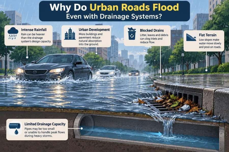

A heavy shower begins, and within minutes water is spreading across a city street. It gathers at the kerb, hides lane markings, slows buses, and pushes pedestrians toward shopfronts. Nearby, a storm drain is plainly visible—so why is the road still flooding?
This situation is frustrating because a drainage system seems like a simple promise: rain falls, drains collect it, pipes carry it away. In reality, an urban drainage network has limited capacity, relies on many connected components, and must work under changing conditions.
Road flooding is rarely caused by one dramatic failure. More often, it results from a chain of smaller hydraulic, maintenance, planning, and operational problems that occur at the same time.
Understanding that chain helps civil engineering students diagnose problems more carefully and helps working professionals select solutions that address the actual bottleneck rather than the most visible symptom.
🌧️ Drainage Is a System, Not Just a Drain
A road inlet, commonly called a gully or catch basin, is only the entry point. Water must pass through its grate, an inlet box or chamber, connecting pipes, manholes, larger trunk sewers, and finally an outfall, storage facility, watercourse, or treatment system.
If any downstream part is restricted or already full, water may pond on the road even when the inlet itself is open. This is why field inspection should follow the whole flow path rather than stopping at the grate.
💧 The Basic Capacity Mismatch
Flooding occurs when water arrives at a location faster than the drainage system can accept, convey, store, or discharge it. The excess has to go somewhere, and on a road it becomes surface flow and ponding.
Capacity is not a single number. Inlet capture capacity, pipe flow capacity, available storage, and outfall conditions may each impose a different limit. The smallest effective limit governs the system.
☔ Rainfall Intensity Can Exceed the Design Storm
Drainage networks are generally designed for a selected rainfall event, expressed through an intensity, duration, and return-period approach. They are not usually intended to prevent every possible surface ponding event during every unusually intense storm.
A short, intense burst may overwhelm a network even when the total daily rainfall is modest. A system can also perform acceptably in a long steady rain yet struggle when most water arrives in a few minutes.
This does not automatically mean the design was wrong. It does mean that safe overland flow routes and acceptable flood depths should be considered when capacity is exceeded.
🛣️ Impervious Surfaces Create Rapid Runoff
Roofs, asphalt, concrete pavements, and compacted areas allow little infiltration. Rain that might have soaked into vegetated soil is converted quickly into runoff and directed toward low points.
Urbanisation changes both runoff volume and timing. A paved catchment acts more like a smooth tray than a sponge: water reaches drains sooner, often causing a sharper peak flow.
🏗️ Redevelopment Can Outgrow Older Networks
A drainage pipe installed decades ago may serve a catchment that has since gained apartment blocks, parking areas, access roads, and hard-surfaced yards. Each project may appear small, but their combined runoff can exceed the assumptions used for the original network.
Changes outside the road corridor matter too. Upstream development can send additional runoff toward an older low-lying street without changing anything visible along that street.
📐 Road Geometry Directs Water to Low Points
Road crossfall, longitudinal grade, kerb shape, and junction layout determine where rainwater travels. Engineers intentionally slope pavements so water reaches the kerb, but that also concentrates flow at sags and low points.
A sag point is especially vulnerable because water arriving from both directions collects there. It often needs more robust inlet arrangements, reliable downstream capacity, and a planned emergency overflow path.
🔍 Inlets Cannot Capture Unlimited Flow
Water flowing along a kerb has momentum. At low flow rates, an inlet may intercept most of it; at higher flow rates, some water can bypass the grate and continue downstream.
Capture also depends on grate orientation, opening area, kerb height, road slope, debris, and the water spread across the carriageway. A large pipe downstream cannot compensate if runoff never enters the system.
🍂 Debris Blocks the First Point of Entry
Leaves, litter, sediment, grass cuttings, plastic bags, and construction material can cover inlet openings. This is a common cause of localised flooding because the blockage may develop quickly during the same storm that produces the runoff.
Maintenance is most effective when it is risk-based. Inlets at sags, near trees, downstream of unpaved areas, and beside busy pedestrian routes typically deserve more frequent inspection than low-risk locations.
🧱 Sediment Reduces Storage and Pipe Area
Fine sediment settles in gully pots, chambers, and flat or slow-moving pipes. Over time it reduces the volume available for temporary storage and narrows the hydraulic flow area.
Sediment often signals an upstream issue: eroding shoulders, poorly controlled construction runoff, damaged verges, or inadequate street cleaning. Removing deposits without addressing their source can create an expensive recurring task.
🕳️ Pipe Defects Restrict Conveyance
Cracks, displaced joints, root intrusion, collapsed sections, and intruding service connections can reduce pipe capacity. Defects may also allow soil to enter the pipe, creating voids around it and increasing the risk of pavement settlement.
Closed-circuit television inspection is commonly used to investigate buried drainage assets. However, observed defects should be interpreted with hydraulic evidence; not every visible crack is the reason for a particular flood.
↩️ Flat Gradients Slow the Network
Gravity drainage depends on elevation difference. Where terrain is very flat, pipes may have limited slope, low flow velocity, and a greater tendency for sediment deposition.
Increasing pipe diameter is not always enough. A large pipe with poor gradient can still operate inefficiently, while a carefully graded system may convey flow more reliably with less frequent sediment buildup.
🌊 Downstream Surcharging Pushes Water Back
A pipe is surcharged when it flows full and pressure rises above the pipe crown. Water may then back up through manholes or inlets, preventing new road runoff from entering.
This is an important distinction: a flooded inlet may be blocked from below rather than blocked at the surface. Cleaning its grate alone will not resolve a downstream surcharge problem.
🏞️ High Outfall Levels Create Backwater
Where a drainage pipe discharges to a river, canal, tidal waterbody, or another sewer, a high receiving-water level can impede discharge. The elevated downstream water level creates a backwater effect that reduces available pipe capacity.
Outfalls need assessment under realistic wet-weather conditions. A pipe that drains freely on a dry inspection day may behave very differently when the receiving channel is high.
🚧 Construction Changes Runoff Before Work Is Finished
Construction sites can expose soil, interrupt existing swales, block temporary drainage paths, and wash sediment toward gullies. Temporary stockpiles or poorly placed barriers may redirect water into roads and properties.
Temporary drainage deserves engineering attention, not just housekeeping. The highest risk may occur before permanent inlets, pipes, and surface finishes are completed.
🏘️ Private Connections Can Affect Public Roads
Driveways, building downpipes, basement drainage, and private paved areas may alter the way runoff reaches a public street. Unauthorised or poorly arranged connections can add flow at unexpected points or introduce sediment and debris.
Responsibility boundaries can complicate diagnosis. The road authority may manage the gully, while the obstruction or excess runoff originates on adjacent private land.
🚦 Junctions and Kerb Openings Create Complex Flow Paths
At intersections, dropped kerbs, pedestrian crossings, cycle tracks, and driveways interrupt the continuous kerb channel. Water may cross the carriageway, concentrate around crossing points, or enter side streets.
Small level changes can have large effects. A resurfacing layer, a poorly matched utility reinstatement, or a raised crossing can create a local ridge that traps water before it reaches an inlet.
🚗 Traffic Turns Ponding into a Safety Problem
Standing water reduces tyre contact with the road surface and can conceal potholes, damaged covers, and lane markings. Vehicles also generate waves that can push water onto footways or into nearby buildings.
For pedestrians, flooded crossings create slip hazards and may force people into traffic. The seriousness of road flooding should therefore be judged not only by depth, but also by speed, location, traffic conditions, and exposure of vulnerable users.
⚡ Pumped Systems Have Operational Dependencies
Some low-lying areas rely on pumps rather than gravity alone. Their performance depends on power supply, controls, pump condition, wet-well capacity, and maintenance.
Backup power, alarms, manual operating procedures, and access for maintenance can be as important as pump size. A pump station is not a passive pipe; it is an operational asset that must function during severe weather.
🌡️ Changing Rainfall Patterns Challenge Old Assumptions
Rainfall records and design guidance are periodically updated because climate conditions and local understanding evolve. More intense short-duration rainfall can place particular pressure on urban networks designed around older assumptions.
Engineers should avoid treating climate allowance as a simple universal number. Appropriate assessment depends on the governing guidance, project life, location, catchment response, and consequences of flooding.
🧮 Models Are Useful but Only as Good as Their Inputs
Hydraulic models help engineers test how runoff moves through pipes and across the ground. They can compare options such as larger pipes, storage tanks, additional inlets, or altered road levels.
But models require assumptions about rainfall, catchment area, surface roughness, pipe condition, and downstream levels. Field survey, maintenance records, flood observations, and asset inspection are needed to check whether the model represents reality.
📊 A Simple Diagnostic Framework
When a road floods, begin by identifying where the water enters, where it should travel, and where it should leave. Then distinguish between a local capture problem and a network or outfall problem.
| Observed condition | Likely mechanism to investigate | Useful first check |
|---|---|---|
| Water pools beside one inlet | Blocked grate, silted gully, local surface depression | Inspect inlet and surrounding levels |
| Several inlets overflow together | Downstream surcharge or restricted trunk pipe | Check manholes and network levels |
| Flooding occurs only near a river or tide | Backwater at outfall | Compare flooding time with receiving-water level |
| Flooding started after nearby works | Changed runoff path, sediment, or altered road profile | Review pre- and post-work drainage routes |
These clues do not prove a cause on their own. They provide a disciplined starting point for inspection and analysis.
🧭 Surface Routing Is a Deliberate Design Layer
When underground drainage is exceeded, the surface becomes a secondary drainage system. Roads, verges, open spaces, and designated channels can guide excess water away from buildings and critical infrastructure.
This approach is sometimes described as designing for exceedance. It accepts that extreme events can exceed pipe capacity and focuses on reducing the consequences of where the water goes next.
🌿 Sustainable Drainage Reduces the Peak
Sustainable drainage systems, often called SuDS, aim to slow, store, infiltrate, filter, and reuse runoff near where it falls. Examples include permeable paving, rain gardens, swales, detention basins, and green roofs.
They are not a universal substitute for pipes. Infiltration may be unsuitable where groundwater is high, soils are poorly draining, contamination is a concern, or underground utilities limit space. Their value comes from matching the measure to site conditions and maintaining it properly.
🧰 Storage Can Protect Constrained Pipes
Detention storage temporarily holds runoff and releases it at a controlled rate. It can be provided in ponds, underground tanks, oversized pipes, modular systems, or landscaped depressions.
Storage is especially useful where downstream pipes or outfalls cannot readily be enlarged. However, it must be designed with safe overflow, access for cleaning, sediment management, and realistic assumptions about how quickly it empties.
🔧 Maintenance Is Part of Design Performance
A drainage design that works only when perfectly clean is vulnerable in the real world. Designers should consider debris load, access for crews, inspection frequency, spare parts, and safe working space from the beginning.
Asset records also matter. Knowing inlet locations, pipe sizes, outfall levels, previous blockages, and inspection history allows maintenance teams to target effort where it has the greatest flood-reduction value.
❌ Common Fixes That Miss the Real Cause
Adding one more inlet may help if the issue is bypass flow, but it will not solve an already surcharged downstream sewer. Enlarging a local pipe may similarly shift the bottleneck farther downstream.
- Cleaning only the visible grate: ineffective when the pipe or outfall is restricted.
- Deepening a local low point: may increase storage on the road rather than remove it.
- Raising kerbs without a route: can protect one edge while trapping water in the carriageway.
- Relying on a pump alone: leaves the system exposed to operational failure and power loss.
The appropriate remedy follows diagnosis. A solution should be tested against both ordinary storms and conditions where the drainage network is exceeded.
📝 Practical Questions for Site Investigations
A good site visit combines observation with simple questions. Speak with maintenance staff and local users when possible; recurring flood patterns often reveal conditions not captured in drawings.
- Does ponding begin at one inlet or across a wider area?
- Does it occur after a particular rainfall pattern, season, tide, or upstream activity?
- Are there signs of sediment, debris, surcharge, or road settlement?
- Has resurfacing, redevelopment, utility work, or landscaping changed local levels?
- Where does water travel once it leaves the intended kerb line?
Photographs should record flow directions, inlet condition, road levels, and safe reference points. Observations during or shortly after rainfall can be particularly informative, provided site safety is maintained.
🤝 Flood Resilience Requires Coordination
Road drainage can involve highway engineers, drainage authorities, water utilities, planners, developers, landscape designers, emergency teams, and property owners. Each party may control a different part of the problem.
Coordination is needed because runoff does not respect administrative boundaries. A resilient solution may combine highway inlet upgrades, planning controls upstream, private-site storage, maintenance changes, and improved downstream outfall management.
🎯 The Core Principle: Find the Bottleneck and the Overflow Route
Urban roads flood despite drainage systems when the complete system cannot handle the actual combination of rainfall, runoff, inlet capture, pipe condition, downstream water level, and surface geometry. The visible water location is not necessarily the failure location.
The most reliable approach is to identify the controlling bottleneck, verify it with site evidence and hydraulic assessment, then provide both adequate routine drainage and a safer path for excess water. Pipes, inlets, storage, landscape measures, maintenance, and emergency routing work best as connected layers rather than isolated fixes.
A drainage system protects an urban road only when every link—from the falling rain to the final outfall, and to the planned overflow route—works together. 🌧️🛣️💧