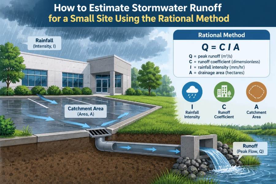

A small parking-area expansion, a new roof, or a compact residential development can change a site’s drainage behavior more than its size suggests. Rain that once soaked into lawn or shallow soil may instead run quickly across asphalt, concrete, and roof surfaces.
For a civil engineer, the immediate question is practical: how much water must the inlet, swale, pipe, or culvert carry during a design storm? An undersized system can pond water against a building or flood a drive. An oversized system can add unnecessary excavation and cost.
The Rational Method is one of the most common screening and design tools for answering that question on small drainage areas. Its appeal is simple: it combines runoff potential, rainfall intensity, and drainage area into a peak-flow estimate.
That simplicity is useful, but it also creates responsibility. A reliable result depends less on pressing calculator buttons than on selecting defensible inputs and recognizing when the method no longer fits the site.
🌦️ What the Rational Method Estimates
The Rational Method estimates the peak runoff rate: the largest instantaneous discharge expected at a chosen drainage point during a selected design storm. The result might be used to size a storm sewer, curb inlet, ditch crossing, or small detention outlet.
It does not calculate the total volume of runoff over an entire storm hydrograph. In other words, it tells a designer how high the peak may be, not how the flow rises and falls over time.
🧮 The Core Rational Method Equation
In customary U.S. units, the familiar equation is:
Q = C i AWhere Q is peak flow in cubic feet per second (cfs), C is the runoff coefficient, i is rainfall intensity in inches per hour, and A is drainage area in acres.
In SI practice, a common form is Q = 0.00278 C i A, where Q is in cubic metres per second, i is in millimetres per hour, and A is in hectares. Always verify the form required by the governing agency; mixing unit systems produces meaningless results.
🎯 Why Peak Flow Matters on Small Sites
Drainage structures respond to flow rate. A pipe has a finite capacity, an inlet can bypass water when overwhelmed, and a shallow channel can overtop when its conveyance is exceeded.
For a compact site, impervious cover and short flow paths often produce rapid runoff. The Rational Method is particularly suited to such settings because its basic assumptions are most reasonable where drainage response is quick and relatively uniform.
📐 Where the Method Is Appropriate
The method is generally used for small urban or suburban drainage areas, especially where land cover is readily identified and the drainage outlet is clear. Local manuals often establish an upper drainage-area limit, and that limit should control the design decision.
It is less suitable for large watersheds, extensive rural catchments, locations with significant storage, or systems where runoff timing matters. A watershed with ponds, broad floodplains, long channels, or multiple distinct subareas may need a hydrograph-based method instead.
⚠️ The Assumptions Behind the Equation
The Rational Method assumes rainfall intensity is spatially uniform over the catchment and remains effectively constant for a duration at least equal to the time of concentration. It also assumes the selected coefficient reasonably represents the catchment’s runoff response.
Real storms and real sites are more complex. Rainfall varies, soils become wetter, and runoff may be delayed by depressions or structures. Treat the output as a design estimate produced under defined assumptions, not as a precise prediction of every storm.
🗺️ Start by Delineating the Drainage Area
Before selecting any coefficient or rainfall value, identify the exact land area that drains to the point being designed. Use contours, proposed grading, curb lines, roof drain connections, swales, and collection structures.
A drainage divide may be obvious on a natural hillside but subtle on a paved site. A curb opening, cross slope, or small ridge can direct runoff away from the structure under review. The correct area is the contributing area, not simply the property boundary.
🏗️ Use Proposed Conditions for Design
For new construction, design storm infrastructure is usually checked using proposed grading and proposed land cover. A project that replaces grass with pavement can have a significantly different runoff response even if its boundary does not change.
Existing conditions can still be useful for comparing impacts or satisfying permit requirements. Keep the two cases separate; do not combine existing drainage paths with proposed impervious-area totals.
🧩 Divide Complex Sites into Subareas
Many sites contain roofs, pavement, landscaped areas, and different flow paths. Dividing the catchment into subareas often makes the analysis clearer and prevents a broad average from hiding an important local condition.
For example, a roof may connect directly to a storm pipe while nearby landscaping drains through a swale. They may share a downstream outlet, but their coefficients and times of concentration can differ.
🧱 Understand the Runoff Coefficient C
The runoff coefficient, C, is a dimensionless representation of how readily rainfall becomes direct runoff. Higher values indicate that a greater portion of rainfall is expected to appear rapidly at the outlet.
Impervious surfaces generally receive high coefficients because water cannot infiltrate through them. Pervious ground usually receives lower values, although compacted soil, steep slopes, sparse cover, and wet antecedent conditions can all increase actual runoff.
🛣️ Select Coefficients from the Correct Standard
Use a coefficient table adopted by the project’s local drainage manual, municipality, transportation agency, or client standard. Tables differ because they may reflect regional rainfall patterns, soil assumptions, return periods, and local calibration practices.
Typical categories include roofs, asphalt or concrete paving, gravel, maintained turf, woodland, and various residential densities. Do not treat a value copied from an unrelated textbook or online source as automatically acceptable for a permitted design.
⚖️ Calculate a Composite Runoff Coefficient
If subareas drain to the same point under the same design rainfall intensity, a composite coefficient can be calculated as an area-weighted average:
Cw = (C1A1 + C2A2 + ... + CnAn) / AtotalThis calculation gives larger surfaces appropriate influence. A small lawn should not dilute the effect of a much larger parking lot simply because the site is described generally as “mixed use.”
| Surface | Area (acres) | Assumed C | C × A |
|---|---|---|---|
| Roof | 0.20 | 0.95 | 0.190 |
| Pavement | 0.35 | 0.90 | 0.315 |
| Landscaping | 0.45 | 0.30 | 0.135 |
| Total | 1.00 | Composite = 0.64 | 0.640 |
The coefficients above are hypothetical only. Actual values must come from the applicable design criteria.
🌱 Pervious Does Not Always Mean Low Runoff
A landscaped area can generate meaningful runoff when soil is compacted during construction, slopes are steep, or grass cover is thin. Fill slopes and frequently trafficked “green” spaces are often less permeable than their appearance suggests.
Field observation helps. Look for rills, bare ground, standing water, and concentrated overland-flow paths. These clues may reveal that the assumed drainage behavior needs closer review.
⏱️ Define Time of Concentration
The time of concentration, usually written as Tc, is the estimated travel time from the hydraulically most distant point of the drainage area to the point of interest. It is not necessarily the farthest straight-line distance.
At a duration equal to Tc, the method assumes the whole catchment is contributing to flow at the outlet. That is why Tc determines the rainfall duration used to select intensity.
🚶 Trace the Longest Hydraulic Flow Path
Trace water as it would actually move: perhaps as sheet flow across a lawn, shallow concentrated flow in a swale, gutter flow along a curb, and finally pipe flow to an inlet or outfall. Sum the travel times for the relevant segments.
The controlling path may begin on a distant grassy slope rather than at the farthest roof corner. Site plans, spot grades, and proposed drainage details should all agree with the path used in the calculation.
📏 Estimate Travel Time Carefully
Travel time is influenced by length, slope, surface roughness, flow depth, and conveyance type. Local design criteria may prescribe accepted equations or minimum Tc values for sheet flow, shallow concentrated flow, gutters, and pipes.
Do not assign an unrealistically short Tc just because a site is small. Very short durations correspond to very high rainfall intensities, so an aggressive assumption can greatly increase the calculated peak flow.
🌧️ Choose the Correct Design Storm Frequency
The selected return period reflects the level of service and consequence of failure. A minor parking-lot inlet, a building-protection system, and a roadway crossing may be governed by different storm frequencies under the applicable criteria.
A return period is a statistical description, not a schedule. A “10-year” design storm does not mean it occurs exactly once every ten years; it describes an annual probability under the rainfall-frequency model being used.
📊 Obtain Rainfall Intensity from IDF Data
Intensity-duration-frequency, or IDF, data relate rainfall intensity to storm duration and selected frequency. For the Rational Method, choose the intensity corresponding to the design return period and a duration equal to Tc.
IDF values should come from the source specified by local criteria or the project’s accepted rainfall data. Confirm the duration units, interpolation approach, and whether the table or curve reports intensity rather than rainfall depth.
🔗 Match Rainfall Duration to Tc
If a catchment has a Tc of 15 minutes, use the design-storm intensity associated with a 15-minute duration. Using a one-hour intensity because it is easier to find will normally understate the short-duration intensity relevant to a fast-responding site.
Where Tc falls between published durations, follow the agency’s direction on interpolation or conservative selection. Document the choice so another reviewer can reproduce the calculation.
🧪 A Complete Hypothetical Calculation
Consider the one-acre mixed-surface site in the earlier table. Its area-weighted runoff coefficient is 0.64. Suppose the calculated Tc is 15 minutes and the applicable IDF data provide a hypothetical 15-minute intensity of 4.2 inches per hour for the selected design frequency.
Q = C i A
Q = 0.64 × 4.2 × 1.00
Q = 2.69 cfs
The estimated peak runoff rate at the outlet is 2.69 cfs. This result is only illustrative: changing the local coefficient table, design storm, Tc procedure, or drainage routing can change the appropriate design flow.
🔍 Check Units Before Trusting the Answer
Unit errors are among the easiest drainage mistakes to make and the hardest to spot after a calculation has been copied into a report. The customary form Q = CiA gives cfs only when intensity is in inches per hour and area is in acres.
Do not insert square feet, hectares, millimetres per hour, or litres per second into that form without the proper conversion. Write units beside every input and perform a quick reasonableness check on the output.
🚧 Account for Routing and Structure Locations
Flow should be calculated at meaningful points in the drainage system. The flow entering an upstream inlet may be smaller than the flow in a downstream pipe that receives several inlets and subareas.
Where travel times differ substantially, simply adding independently calculated peak flows can be conservative or misleading depending on the required procedure. Follow the governing method for combining subareas, timing, and any required hydrograph routing.
🕳️ Do Not Confuse Inlet Capacity with Pipe Capacity
A pipe large enough to carry the calculated discharge does not guarantee that water can enter it. Curb inlets, grate inlets, and catch basins have interception limits affected by approach flow, slope, ponding depth, debris, and bypass conditions.
Check each part of the drainage chain: surface collection, inlet capture, pipe conveyance, junction behavior, outlet condition, and safe overflow route. The smallest practical bottleneck can control system performance.
🏞️ Consider Downstream Conditions
The Rational Method gives flow arriving at an outlet, but downstream water levels can affect whether the system works. A high tailwater in a ditch, pond, or receiving pipe can reduce outlet capacity and cause upstream surcharging.
Check the discharge location, erosion potential, receiving-system capacity, and whether a protected emergency overflow path exists. Drainage design is a connected system, not just a single calculated pipe.
🌿 Recognize the Role of Detention and Green Infrastructure
Bioretention, permeable pavement, vegetated swales, cisterns, and detention basins can reduce or delay runoff when properly designed. Their benefit cannot be represented by casually choosing a lower C value unless the governing criteria explicitly allow that approach.
These practices involve storage, infiltration, underdrains, overflow structures, soil media, and maintenance. A storage-routing or continuous-simulation analysis may be more appropriate when their performance is central to the design.
🧰 Build a Transparent Calculation Sheet
A good Rational Method worksheet allows a reviewer to retrace every decision. Include a drainage map, subarea labels, surface areas, coefficients and their sources, flow-path sketch, Tc segments, IDF input, equation form, and final flow at each design point.
Spreadsheets are helpful, but formulas should remain visible and protected from accidental unit changes. Clear documentation is especially valuable when grading revisions change a divide or add impervious area late in design.
❌ Common Mistakes to Avoid
- Using the total parcel area when only part drains to the structure.
- Applying a single coefficient without checking the mix of surfaces.
- Selecting rainfall intensity for the wrong duration or return period.
- Ignoring proposed grading, curb lines, roof leaders, or off-site inflow.
- Using a pipe-flow travel time without confirming the pipe is part of the controlling path.
- Assuming a downstream system has unlimited capacity.
- Rounding inputs too early and losing traceability.
Most of these errors are not mathematical. They come from an incomplete understanding of where water goes and how the local design standard defines the calculation.
🧭 Know When to Use Another Method
Move beyond the Rational Method when a project requires runoff volume, hydrograph timing, pond routing, channel routing, floodplain analysis, or detailed storage performance. Larger and more complex drainage systems often need methods that represent changing rainfall and watershed response over time.
The Rational Method remains valuable as a preliminary tool and for many small conveyance designs. Choosing a more detailed method is not a criticism of the equation; it is a response to a different engineering question.
📝 Review the Result with Engineering Judgment
Compare the calculated discharge with the site’s scale. Does a compact roof-and-pavement area produce a value in a plausible range? Does the selected Tc match the visible length, slope, and flow path? Does the contributing area exclude land that drains elsewhere?
Then test the physical design. Verify that proposed grades lead water toward intended collection points and that water has a safe path if an inlet clogs or a storm exceeds the design event.
✅ The Core Principle to Remember
The Rational Method is most reliable when it is treated as a disciplined chain of decisions: define the contributing area, represent surfaces with appropriate coefficients, determine a credible time of concentration, and select rainfall intensity that matches that time and the required storm frequency.
The equation is short, but every term contains a site-specific engineering judgment. A carefully delineated one-acre site with documented assumptions is more useful than a polished calculation based on guessed inputs.
Estimate runoff by understanding the path water takes across the site first, then use the Rational Method to translate that physical understanding into a defensible peak flow. 🌧️📐🏗️