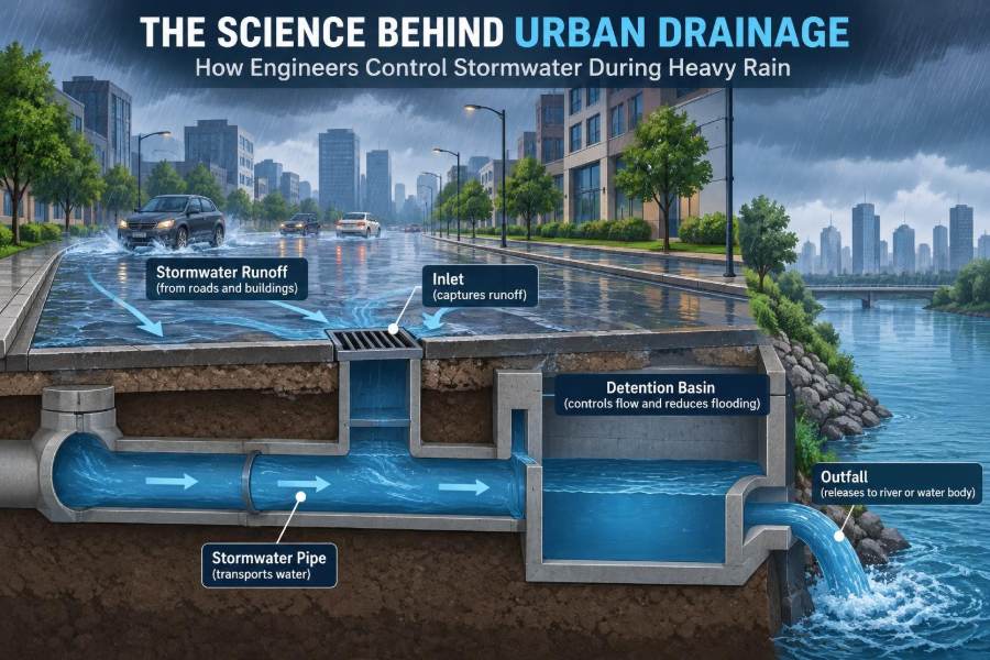

A hard afternoon rain can turn an ordinary street into a shallow river within minutes. Water sheets across parking lots, gathers at kerbs, disappears into grated inlets, and—if the system is overwhelmed—begins to pool at intersections, underpasses, and building entrances.
Most people notice urban drainage only when it fails. Yet beneath roads, parks, and sidewalks is a deliberately planned network that must manage water moving from thousands of roofs, driveways, and streets at the same time.
Designing that network is not simply a matter of making pipes larger. Engineers must estimate how much rain may fall, how quickly it will become runoff, where it can safely go, and what happens when a storm exceeds the design assumption.
Urban drainage is therefore a blend of hydrology, hydraulics, land planning, maintenance, and risk management. Understanding its logic makes flooded streets—and the infrastructure intended to prevent them—far easier to read.
🌧️ Stormwater Is Rainwater on the Move
Stormwater is rainfall or snowmelt that flows across the ground rather than soaking into soil or remaining on a surface. In a natural landscape, vegetation, depressions, and permeable soil slow much of this water and allow infiltration.
In a city, the journey is usually faster. A drop falling on a roof may enter a downpipe, cross a paved area, reach a gutter, pass through an inlet, and travel into an underground pipe within a short time.
The engineering challenge is not to stop rain. It is to control the water’s path, speed, depth, and destination so that people, property, transport routes, and waterways are protected as reasonably as practicable.
🏙️ Why Urban Development Changes the Water Cycle
Urbanization replaces soil and vegetation with roofs, asphalt, concrete, and compacted ground. These surfaces are largely impervious: water cannot readily pass through them.
That change increases runoff volume and reduces the time available for water to drain naturally. It also removes small natural storage features such as shallow hollows, leaf litter, and vegetated channels.
A useful comparison is a sponge and a tray. Undisturbed soil often behaves more like a sponge, accepting water until it becomes saturated. A paved district behaves more like a tilted tray, quickly directing water toward its lowest edges.
💧 Runoff Begins When Storage and Infiltration Are Exceeded
Not every rainfall event creates the same amount of runoff. At the beginning of a light shower, water may wet surfaces, fill tiny cracks, collect in surface depressions, and infiltrate into exposed ground.
Runoff increases when rainfall intensity exceeds the rate at which soil can absorb water or when the surface offers little opportunity for infiltration. Saturated ground, frozen ground, clogged surfaces, and dense paving all make this happen sooner.
Engineers commonly describe the tendency of an area to produce runoff using a runoff coefficient. Higher values represent surfaces that convert a greater share of rainfall into direct flow, although the exact value depends on site conditions and the design method used.
⏱️ Rainfall Intensity Matters More Than Rainfall Total
A day-long gentle rain can deliver more total water than a brief cloudburst, yet the cloudburst may create the more serious drainage problem. Pipes and inlets are limited by the rate at which they can accept and convey flow.
Engineers therefore consider rainfall intensity, commonly expressed as depth per unit time, alongside total rainfall depth. High-intensity rainfall can generate a sharp flow peak before upstream parts of the system have time to drain.
Local rainfall records are used to develop design relationships between storm intensity, duration, and estimated rarity. These relationships help designers choose an event appropriate to the consequences of flooding at a particular site.
🕒 Time of Concentration Sets the Critical Moment
The time of concentration is an estimate of how long it takes runoff from the hydraulically most distant part of a catchment to reach its outlet. It includes travel over land, along gutters, through channels, and inside pipes.
Before that time, only part of the catchment contributes to the outlet flow. Around that point, runoff from much of the area may arrive together, producing a critical peak.
A compact paved development can have a short time of concentration because water moves quickly. A larger catchment with vegetation, flatter slopes, or storage areas may respond more slowly, though it can still produce substantial volumes.
🗺️ The Drainage Catchment Is the Real System Boundary
A drainage system is designed around its catchment: the land area that drains to a shared point. Catchment boundaries are governed by terrain, kerb lines, grading, walls, roads, and pipe connections—not merely by property lines.
Small changes in levels can redirect large quantities of water. A driveway crest, a raised threshold, or a new retaining wall may divide flows differently from what a contour map first suggests.
This is why site surveys and drainage plans matter. Before sizing infrastructure, engineers need to know where water currently travels and where it will travel after construction.
📐 Surface Grading Creates the First Drainage Network
The visible surface is the first and often most important part of urban drainage. Road crowns, crossfalls, kerbs, swales, yards, landscaped areas, and paved slopes guide water toward intended collection points.
A road is typically shaped so water drains toward one or both sides rather than remaining in wheel paths. Kerbs then act as shallow channels, carrying flow longitudinally toward inlets.
Poor grading can defeat an otherwise adequate underground network. If water is trapped by a local low point or directed toward a building door, a large downstream pipe cannot solve the immediate surface hazard.
🕳️ Inlets Are the Gateway from Street to Pipe
Stormwater inlets—often called catch basins, gullies, or grated drains—transfer surface flow into the underground system. Their placement is as important as their number.
Inlets are usually located at low points, sag points, corners, and intervals along long kerb runs. They must intercept water before the spread across a roadway becomes unsafe or reaches vulnerable entrances.
An inlet has a practical intake limit. During intense flow, water can pass over a grate, bypass a kerb opening, or be obstructed by leaves and litter. Designers account for this by considering inlet type, slope, ponding depth, approach flow, and blockage risk.
🧹 Debris Can Turn a Small Weakness into Local Flooding
Leaves, plastic packaging, sediment, and grass clippings often accumulate where flow slows near an inlet. Even a well-designed grate may lose much of its effective opening when debris mats across it.
Maintenance crews therefore clean known problem locations before and during wet seasons where practical. Inspection is especially valuable after construction, landscaping work, or storms that transport sediment.
For property owners, sweeping material away from a street inlet can reduce nuisance ponding, but safety rules and local authority procedures should always be followed. Never remove grates, enter drainage structures, or attempt to clear flowing underground pipes.
🔩 Pipes Convey Water Under Roads and Buildings
Once captured, stormwater commonly moves through gravity pipes. The pipe needs enough slope to maintain flow, but urban utilities, shallow cover, road levels, and downstream outfalls often constrain the available gradient.
Pipe capacity depends on diameter, slope, internal roughness, and the depth of flow. A full pipe does not simply mean water stops moving; under surcharge conditions it may continue flowing under pressure, but the system has less reserve capacity.
Engineers also consider minimum velocities where sediment deposition is a concern. A pipe that is oversized for frequent small storms may carry water too slowly to keep fine material moving, creating a different maintenance problem.
🔵 Manholes Provide Access, Changes, and Inspection Points
Manholes are chambers placed at pipe junctions, changes in direction, changes in slope, and intervals along long runs. They allow inspection, cleaning, and maintenance equipment to reach the network.
They also manage hydraulic transitions. Abrupt changes in direction or elevation can create energy losses, turbulence, and sediment accumulation, so chamber details matter more than their simple appearance suggests.
Access structures must be designed and maintained with public safety in mind. Covers should remain secure and level with the surrounding surface, while entry into confined spaces is a specialist activity requiring strict controls.
📊 How Engineers Estimate Peak Runoff
For relatively small catchments, designers may use a simplified approach that relates peak flow to rainfall intensity, catchment area, and runoff characteristics. Larger or more complex systems often require rainfall-runoff models that represent storage, routing, land cover, and time variation in greater detail.
No calculation removes uncertainty. Rainfall varies by location and storm pattern, land use changes over time, and real networks contain partial blockages, construction tolerances, and unexpected connections.
Good design makes assumptions visible. It records the contributing area, surface types, selected storm event, flow paths, and allowable ponding so that future engineers can understand the basis of the system.
📏 Design Storms Reflect Consequences, Not a Single Universal Rule
A design storm is a rainfall event selected for engineering analysis. Its severity is chosen according to local requirements, the asset being designed, and the consequences if water exceeds the system’s capacity.
A minor local access road and a hospital entrance should not necessarily be treated as identical risks. Critical transport corridors, dense developments, emergency routes, and locations with limited safe overflow paths often justify more conservative assessment.
Requirements vary between jurisdictions and projects. Engineers must use the applicable local standards, drainage authority guidance, and project-specific flood information rather than transferring a rule of thumb from another city.
🌊 Minor Systems and Major Systems Work Together
Urban drainage is often understood as two linked systems. The minor system includes inlets, pipes, small channels, and other infrastructure intended to handle more frequent rainfall events.
The major system is the planned surface route used when rainfall exceeds minor-system capacity. Roads, open spaces, swales, and designated overland flow paths can carry or temporarily store water away from buildings.
This distinction accepts an important reality: designing every pipe for every conceivable storm is rarely practical. Safer cities provide a controlled backup route instead of allowing excess water to find unpredictable paths.
🛣️ Streets Can Function as Emergency Flow Paths
During an extreme event, water may flow along the road surface even when the underground network is functioning. This is not automatically a design failure if depths, velocities, routes, and building protection have been considered.
Road profiles can direct excess flow away from homes and toward lower-risk storage areas or watercourses. Conversely, an underpass, basement ramp, or depressed intersection can become dangerous if the planned flow path leads into it.
Surface flood routing should be checked across property boundaries. Water that safely leaves one development can create a serious problem if it is concentrated onto a neighboring lot or an undersized downstream street.
🏞️ Detention Slows the Peak Flow
Detention stores runoff temporarily and releases it gradually. A detention basin, underground tank, oversized pipe, or landscaped storage area can reduce the peak flow reaching downstream pipes and waterways.
Its purpose is not necessarily to remove water from the site permanently. Instead, it changes the timing: inflow may be rapid during the storm, while outflow is restricted through an outlet structure.
Detention is especially useful where new development would otherwise send runoff downstream faster than the pre-development landscape did. It needs a safe overflow route because storage volume can be exceeded in an unusually large event.
💦 Retention and Infiltration Reduce Runoff Volume
Retention holds water for longer periods, while infiltration practices encourage water to soak into suitable ground. Examples include infiltration basins, soakaways, permeable pavement systems, and bioretention areas.
These approaches can reduce runoff volume, improve water quality, and support greener public spaces. But they depend on soil permeability, groundwater conditions, available land, contamination risks, and reliable maintenance.
Infiltration is not appropriate everywhere. Poorly drained soils, steep slopes, unstable ground, high groundwater, or proximity to certain foundations and contaminated land may limit its use. Site investigation is essential before relying on it.
🌿 Green Infrastructure Uses Landscape as Infrastructure
Green infrastructure manages stormwater through vegetation, soil, and natural processes. Rain gardens, planted swales, tree pits, green roofs, wetlands, and vegetated filter strips can intercept, slow, filter, and store runoff.
A rain garden is not simply decorative planting. It is a shallow engineered basin that receives runoff, ponds it briefly, and uses a designed soil profile and drainage arrangement to manage water.
These systems offer co-benefits such as shade, habitat, and improved streetscape quality. Their performance, however, depends on correct grading, healthy vegetation, inlet protection, and periodic removal of sediment and litter.
🧱 Permeable Pavement Has a Specific Job
Permeable pavement allows water to pass through joints or pores into an aggregate layer beneath. That layer temporarily stores water before it infiltrates into soil, drains through an underdrain, or both.
It can be effective in low-speed areas such as parking bays, plazas, walkways, and some lightly trafficked roads. It is not a universal substitute for conventional pavement because structural loading, clogging potential, winter maintenance, and subgrade conditions require careful evaluation.
The key detail is often the surface drainage area. If sediment-laden runoff from an adjacent unpaved area is directed onto permeable pavement, its pores may clog much faster than expected.
🧪 Stormwater Quality Is Part of Drainage Design
Runoff can carry sediment, oils, metals, nutrients, tire particles, litter, and other pollutants from urban surfaces. The first portion of runoff after a dry period can mobilize accumulated material, though pollutant patterns vary greatly by land use and storm conditions.
Water-quality measures may include sediment forebays, vegetated filters, hydrodynamic separators, oil-control devices, treatment wetlands, and bioretention systems. Their selection should match the pollutant source and the receiving water’s sensitivity.
Quantity control and quality control are related but different. A tank that slows peak flow may provide little treatment unless its configuration promotes settling or filtration; a planted filter may have limited flood-storage capacity without adequate design volume.
🔀 Combined Sewers Require Special Attention
Some older cities have combined sewer systems, where stormwater and wastewater share the same pipes. During dry weather, the system carries sanitary flow to treatment facilities.
Heavy rain can add volumes that exceed available pipe or treatment capacity. Such networks use storage, control structures, separation projects, and operational strategies, but their constraints differ substantially from separate storm-drain networks.
Where systems are separate, storm drains should not receive sewage, and sanitary sewers should not receive roof or yard runoff unless specifically authorized. Incorrect cross-connections can overload infrastructure and create public health or environmental problems.
🌉 Outfalls Connect the City to Its Receiving Waters
An outfall is where a drainage system discharges to a river, lake, sea, ditch, or other downstream channel. Its condition can control how well the entire upstream network drains.
High water levels in the receiving water can create tailwater, reducing the available slope and backing water up through pipes. Tides, river floods, debris at the outlet, and erosion around the outlet all need consideration.
Outfall structures often include erosion protection because fast discharge can scour soil and undermine banks. In sensitive waterways, designers also consider energy dissipation, habitat impacts, and permit requirements.
🔄 Pumps Are Used When Gravity Is Not Enough
Gravity drainage is generally preferred because it works without continuous power. Yet low-lying underpasses, basements, coastal areas, and flat terrain may require pumping where a gravity outlet is unavailable.
A pump station introduces operational dependencies: power supply, controls, backup power where warranted, debris screening, alarms, access for maintenance, and storage for inflow during pump outages.
Pumps can be highly effective when designed and operated properly, but they should not hide poor site planning. If a development can avoid placing a critical entrance at the bottom of a drainage basin, that may be the more resilient choice.
🌡️ Climate Change Requires Forward-Looking Design
Changing rainfall patterns may alter the intensity, duration, seasonality, or uncertainty of future storms in some regions. Sea-level rise can also affect coastal outfalls and groundwater levels.
Engineers respond through updated rainfall guidance where available, sensitivity testing, extra storage, adaptable layouts, protected overland flow routes, and designs that can be upgraded later. The appropriate approach depends on local climate information and the life of the asset.
Resilience does not mean predicting every future storm exactly. It means recognizing uncertainty and avoiding designs that fail abruptly when conditions are somewhat worse than expected.
🏗️ Construction Can Disrupt Existing Drainage
Construction changes drainage long before a building is complete. Soil compaction, temporary stockpiles, exposed ground, blocked inlets, and altered levels can redirect runoff and increase sediment loads.
Temporary drainage and erosion-control measures should be planned early, inspected regularly, and adjusted as the site changes. A sediment fence alone is not a complete stormwater plan if concentrated runoff can bypass it.
Finished levels, roof-drain connections, inlet locations, and detention outlets also need verification before handover. Small deviations in construction can have large effects where water relies on shallow slopes.
🔍 Modelling Must Be Checked Against Real-World Flow Paths
Computer models are valuable tools, but their output is only as reliable as the inputs and assumptions. A model may show adequate pipe capacity while missing a raised kerb, a blocked culvert, or a low doorway that changes the real flood consequence.
Field inspection remains essential. Engineers walk sites during dry weather to identify low points, inlet conditions, evidence of sediment, and likely overflow routes; observations during or after rain can reveal even more.
Model results should be interpreted, not merely accepted. Comparing predicted water levels and routes with survey data, historic observations where reliable, and physical constraints helps expose unrealistic assumptions.
⚠️ Common Urban Drainage Design Mistakes
Many drainage problems arise from overlooked interfaces rather than a single obvious error. The following issues repeatedly deserve attention:
- Assuming pipes alone will manage extreme rainfall without a safe surface overflow route.
- Placing inlets too far apart or overlooking local low points created by grading.
- Sending additional runoff downstream without checking downstream capacity and impacts.
- Using infiltration measures without confirming soil, groundwater, and maintenance conditions.
- Ignoring debris, sediment, and access needs when selecting drainage structures.
- Allowing finished landscaping, walls, or resurfacing to alter intended flow paths.
Each mistake is manageable when identified early. Late corrections are usually more expensive because roads, utilities, buildings, and property boundaries may already constrain the solution.
🧰 Maintenance Is a Design Requirement, Not an Afterthought
Drainage assets age and collect material. Grates clog, basins fill with sediment, vegetation grows, pipe joints shift, pumps wear, and outlet channels erode. A system that performed well at completion may not perform the same way years later.
Designers can make maintenance easier by providing access, using robust details, avoiding unnecessary complexity, and clearly identifying assets on record drawings. Owners need inspection schedules suited to the site’s risks and operating environment.
A practical maintenance plan commonly addresses inlet cleaning, sediment removal, vegetation management, pipe inspection, pump testing, outlet inspection, and post-storm checks at known trouble spots.
🏠 Practical Steps for Buildings and Property Sites
At building scale, drainage begins with keeping water away from foundations and openings. Roof downpipes should discharge to an approved system or properly designed surface treatment, not directly against a wall or onto a neighbor’s property.
Finished ground should generally fall away from buildings where site conditions permit. Basement entries, garage ramps, and low door thresholds need particular attention because they can collect fast-moving surface water.
Property improvements can unintentionally worsen drainage. A new patio, shed, fence base, or raised garden bed may block a former flow path, so proposed changes should be reviewed in relation to existing levels and local requirements.
🤝 Drainage Is a Coordination Problem
Effective stormwater management requires coordination among civil engineers, architects, landscape designers, utility designers, planners, contractors, maintenance teams, and property owners. A drainage line drawn early can be compromised by later changes to foundations, trees, utilities, or access routes.
Coordination is particularly important at boundaries: where private drains connect to public systems, where one parcel discharges toward another, and where a new development changes flow reaching an existing network.
The strongest solutions integrate drainage into the site layout from the beginning. They do not treat it as leftover infrastructure to fit into the narrow spaces remaining after all other decisions are fixed.
🧭 Reading a Street During Heavy Rain
Watching water during a storm is a simple way to understand drainage behavior. Notice where runoff first gathers, whether it follows kerbs as intended, which inlets capture flow, and where water bypasses them.
Also look for signs of a planned major flow path: a broad low road corridor, a swale through open space, or a basin that temporarily ponds. These features may look ordinary in dry weather but can be central to flood resilience.
Never enter moving floodwater or open drainage structures to investigate. The observation is useful precisely because it reveals how quickly conditions can change when water is concentrated.
✅ The Core Principle: Slow, Store, Convey, and Safely Overflow
Reliable urban drainage uses layers of protection. It reduces runoff where feasible, slows water across the surface, captures routine flows, stores excess water, conveys it through pipes or channels, treats pollutants where needed, and provides safe routes when capacity is exceeded.
No single feature is sufficient in every location. Pipes are efficient but limited; green infrastructure is valuable but site-dependent; detention controls peaks but needs space and an overflow plan; surface routing protects the system when rare events exceed assumptions.
The central engineering task is to manage water as a connected system—from raindrop to receiving water—while acknowledging uncertainty, future change, maintenance needs, and the consequences of failure.
Well-designed urban drainage does not make heavy rain disappear; it gives stormwater a safer, slower, and more predictable place to go. 🌧️🏙️💧