
A river crossing can look deceptively simple from the road: a deck, two towers, a few cables, and traffic moving overhead. For the engineers who designed the first major suspension bridges, however, that apparent simplicity concealed a difficult question: how can a relatively slender structure safely carry people, vehicles, wind, and its own weight across a wide obstacle?
Before long-span bridges became practical, a deep valley, tidal estuary, or navigable river could divide markets, communities, and transport networks. Ferries were slow and weather-dependent; masonry arches needed many supports; and timber crossings had limited durability and span.
Early suspension bridges offered a radically different structural idea. Rather than forcing a heavy beam or arch to resist the entire crossing, they used tensioned cables to carry load toward strong anchorages on land.
That choice changed not only bridge appearance, but the engineering of materials, foundations, construction methods, and structural analysis. Modern cable-supported bridges still reflect lessons learned during those early experiments.
🧭 The Long-Span Problem Before Suspension Bridges
Traditional bridge forms worked well where piers could be built economically. Stone arches, for example, transfer load mainly through compression, but their horizontal thrust demands robust abutments and multiple supports for a long crossing.
In deep water or over a shipping channel, each additional pier creates cost, scour exposure, and obstruction. Engineers needed a form that could place most of its support at the ends of the crossing rather than in the middle.
🪢 The Core Structural Idea: Carrying Load in Tension
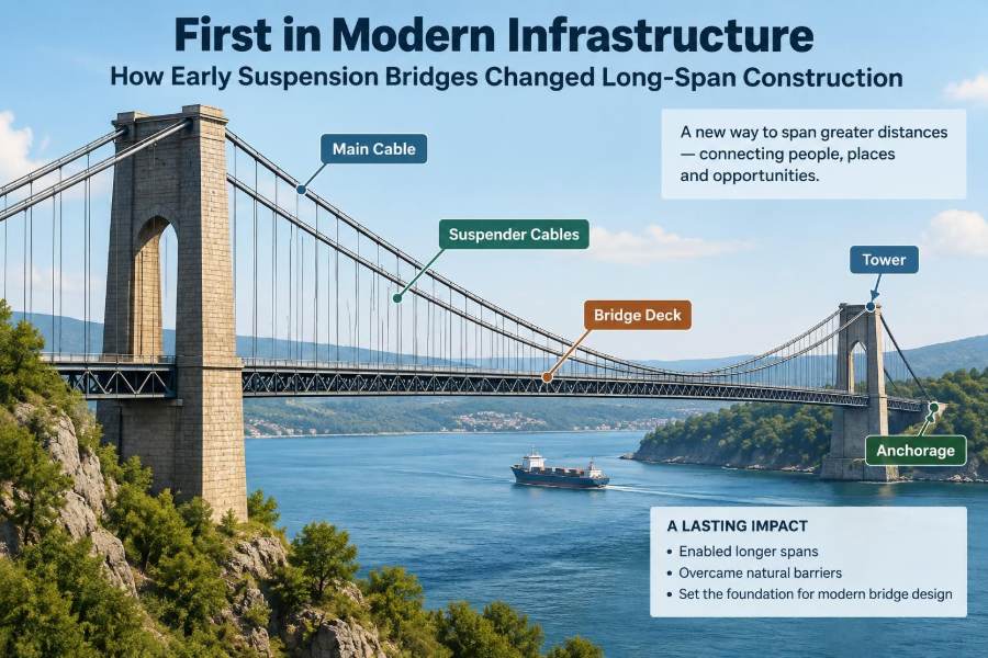
A suspension bridge hangs its deck from vertical members called hangers or suspenders. These transfer deck load to main cables draped between towers and anchored at both ends.
The main cables work primarily in tension: they are pulled rather than crushed. This is a major advantage because iron and later steel can develop high strength in tension with comparatively little material.
🏹 Why a Hanging Cable Takes a Curve
A cable has negligible bending stiffness compared with a beam. When load is applied, it cannot remain straight; it adopts a curve that aligns with the forces acting through it.
Under a uniformly distributed load along the horizontal span, the cable shape is close to a parabola. Under load distributed along the cable itself, it is a catenary. The distinction matters in analysis, although both describe the same essential behavior: load creates tension and sag.
📐 Sag, Tension, and the Price of Flatness
A flatter cable gives a bridge a lower visual profile, but it also increases horizontal force at the anchors and towers. More sag reduces that horizontal force, though it may require taller towers and more clearance below the deck.
This trade-off remains fundamental. Designers cannot select cable geometry for appearance alone; cable sag, tower height, deck elevation, anchor capacity, and site constraints must be considered together.
🗺️ Early Precedents Beyond Europe
Suspension principles existed long before industrial-era iron bridges. Rope bridges in mountainous regions, including the Andes and Himalayas, demonstrated that flexible tensile elements could cross terrain that defeated conventional rigid structures.
These crossings were not simply curiosities. They showed that a bridge could derive strength from geometry, tension, and reliable anchorage. Modern suspension bridges use different materials and analysis, but they retain the same load path.
🌉 Chain Bridges and the First Industrial Leap
Early nineteenth-century suspension bridges often used linked wrought-iron bars or chains rather than wire cables. The links were easier to fabricate with available metalworking methods and made the tensile system visible and understandable.
Chain bridges proved that industrial materials could enable spans beyond the practical reach of many timber or masonry solutions. Yet individual links, pins, and connection details also introduced points requiring careful fabrication and inspection.
🔩 Wire Cables Changed What Was Possible
Wire cable construction brought major advantages. Thousands of small wires could act together, providing redundancy and allowing very large tensile capacity without relying on a single massive bar or chain link.
Wire also made it feasible to form long, continuous cables. This was crucial as spans increased, because cable weight, handling, and connection reliability become increasingly demanding at large scale.
🧵 Cable Spinning as a Construction Innovation
For major bridges, cables could be assembled in place by repeatedly carrying individual wires across the span and compacting them into a bundle. This process, generally called aerial spinning, avoided lifting one enormous completed cable into position.
The method transformed construction logistics. Instead of treating the cable as a finished product delivered to site, engineers made the principal structural element over the crossing itself.
🏗️ Towers Do More Than Create an Iconic Skyline
Bridge towers support the main cables at high points and direct their forces downward into foundations. They experience large vertical loads, but they must also resist bending from unequal live loading, wind, construction stages, and cable geometry.
A tower is therefore not a decorative gateway. Its shape, stiffness, member arrangement, and foundation connection directly affect the bridge’s behavior.
🪨 Anchorages Turn Cable Pull into Ground Force
At each end of a conventional earth-anchored suspension bridge, the main cable transfers a large horizontal pull into an anchorage. That anchorage may rely on massive concrete, competent rock, soil resistance, or a carefully designed combination of these.
Anchorage design begins with geology. A cable with ample tensile strength is of little value if its terminal support can move, rotate, or fail under sustained force.
🌊 Foundations Became a Defining Challenge
Long-span sites are often difficult sites: tidal channels, deep rivers, soft deposits, steep banks, or seismic regions. Early bridge builders learned that impressive superstructure concepts could be undermined by uncertain foundations.
Foundation work demanded site investigation, dewatering methods, cofferdams, caissons, and later more systematic geotechnical practice. The bridge was no longer just a visible deck and cables; much of its safety depended on what could not be seen.
🚢 Navigation Clearance Made Long Spans Valuable
Wide unobstructed spans preserve a channel for vessels. This advantage was especially significant at busy estuaries and harbors, where multiple piers could interfere with navigation and complicate marine construction.
A suspension bridge could place its principal towers near shore and keep the central channel clear. The benefit had to be balanced against the cost of tall towers, heavy anchorages, and long approach structures.
🛤️ The Deck Is a Structural Partner, Not Just a Road
The deck distributes wheel loads to the hangers and helps control the bridge’s overall shape. In early bridges, deck systems were often relatively flexible, which made them vulnerable to movement under traffic and wind.
Modern stiffening girders and trusses give the deck greater bending and torsional resistance. They help spread localized loads and limit excessive deformation, but they also add dead load that the cable system must carry.
⚖️ Dead Load and Live Load Behave Differently
Dead load is the permanent weight of cables, deck, towers, surfacing, and fixed equipment. Live load changes with traffic, pedestrians, maintenance vehicles, or rail operations.
Because cable systems are flexible, an unevenly loaded span can alter cable shape and induce significant force changes. A line of vehicles on one side of a bridge is structurally different from an evenly distributed crowd or empty roadway.
🌬️ Wind Exposed the Limits of Early Assumptions
Wind does not act only as a steady sideways push. It can create fluctuating pressure, lift, torsion, and vibration. A flexible long-span bridge may respond dynamically, meaning its movement depends on time as well as force magnitude.
Early designers did not have modern wind tunnels, sensors, numerical models, or a mature theory of aeroelastic behavior. Their designs necessarily relied more heavily on precedent, simplified calculation, observation, and conservative material use.
🎼 Vibration Is Not Always a Sign of Failure
A bridge can visibly vibrate and still remain structurally sound, but movement must be understood. Vertical bouncing, lateral sway, twisting, and cable vibration may affect comfort, fatigue life, connections, or aerodynamic stability.
The crucial engineering question is not simply, “Does it move?” It is “What mode is moving, what excites it, how much energy is added, and what limits protect the structure?”
🚨 The Tacoma Lesson in Context
The 1940 collapse of the original Tacoma Narrows Bridge became a defining reminder that aerodynamic stability cannot be inferred from static strength alone. The bridge’s dramatic oscillations involved wind-structure interaction and torsional motion.
It was not an “early suspension bridge” in the nineteenth-century sense, but it changed the field built by earlier long-span pioneers. Designers increasingly treated aerodynamics as a central design discipline rather than an afterthought.
🧪 Materials Progressed Alongside Bridge Form
Wrought iron, cast iron, and early steel did not behave identically. Their strength, ductility, production consistency, and susceptibility to defects shaped what engineers could responsibly build.
Material selection also included corrosion resistance and inspectability. A bridge designed for decades of exposure needs details that shed water, protect cable wires, and permit maintenance—not merely high initial strength.
🔍 Redundancy Matters in Tensile Systems
A multi-wire cable can tolerate localized wire damage better than a system dependent on one single tensile element. This does not eliminate risk: corrosion, broken wires, anchorage deterioration, and clamp damage still require detection and repair.
Redundancy is most useful when engineers can inspect the system and understand how damage redistributes force. It is a strategy for managing uncertainty, not permission to neglect maintenance.
🧱 Stiffening Trusses Brought Control to Flexible Spans
Many landmark suspension bridges used deep trusses beneath or alongside the deck. These trusses increased stiffness and helped distribute loads among hangers rather than allowing a concentrated load to create a sharp local dip.
The concept illustrates a recurring engineering pattern: one system provides efficient long-span support, while another controls deformation. The cable and stiffening system must be designed as one interacting structure.
🏛️ The Menai Strait and the Proof of a New Type
Thomas Telford’s Menai Suspension Bridge, opened in 1826, is commonly recognized as a major early demonstration of the suspension form for a critical route. Its location demanded navigation clearance and a crossing more dependable than ferry service.
The bridge did not solve every future problem, but it showed that a suspension bridge could serve strategic transport needs at a scale beyond experimental footbridges. It helped establish the type as serious civil infrastructure.
🏙️ Roebling and the American Long-Span Tradition
John A. Roebling advanced wire-cable bridge practice in the United States through design, manufacture, and construction methods. His work emphasized the practical integration of cable technology, towers, anchorages, and stiffening systems.
The Brooklyn Bridge, completed in 1883 under the leadership of Washington Roebling after John Roebling’s death, became an enduring example of this integrated approach. It combined suspension cables with substantial deck stiffening and conservative structural provision for its era.
🏭 Construction Sequencing Became an Engineering Problem
A bridge does not acquire its final forces all at once. Towers are erected, pilot lines are placed, cables are spun, hangers are installed, and deck sections are added in sequence.
Each stage changes load paths and stability. Temporary works, erection tolerances, cable adjustment, and worker access are therefore part of structural engineering, not merely site logistics.
📏 Measurement Replaced Guesswork Gradually
Early long-span builders used surveying, load tests, material testing, and careful observation, but their analytical tools were limited compared with modern practice. As bridge engineering developed, calculation methods improved for cable geometry, deflection, elastic behavior, and wind response.
Modern software is powerful, yet the earlier lesson remains relevant: a model is only as credible as its assumptions about loads, supports, material properties, and construction sequence.
🧰 What Inspection Teaches Modern Engineers
Inspection of older suspension bridges often focuses on cable condition, corrosion protection, hanger connections, deck drainage, bearings, joints, tower cracks, and anchorage access. Water management is particularly important because trapped moisture accelerates deterioration.
For students and practitioners, the practical insight is simple: durability begins in design details. A member that cannot be inspected, drained, recoated, or replaced may create a long-term risk regardless of its original capacity.
⚠️ Common Misreadings of Suspension Bridge Behavior
Several intuitive assumptions can lead to poor reasoning about cable-supported structures:
- “The cables only carry vertical load.” They also develop large horizontal force at towers and anchorages.
- “A stronger cable solves every problem.” Deck stiffness, foundations, wind response, and connections can govern design.
- “Movement means weakness.” Controlled flexibility can be expected; unacceptable vibration or instability is the concern.
- “Historic bridges were designed by trial and error alone.” They used the best available theory and experience, while also operating with uncertainties later engineering tools reduced.
🔄 Suspension, Cable-Stayed, and Arch Bridges Compared
| Bridge type | Primary force path | Typical long-span advantage | Key constraint |
|---|---|---|---|
| Suspension | Deck to hangers to main cables to towers and anchorages | Very efficient for the longest main spans | Large anchor forces and aerodynamic sensitivity |
| Cable-stayed | Deck directly supported by inclined stays to towers | Stiff, efficient for many medium-to-long spans | Complex stay and deck interaction |
| Arch | Load carried mainly in compression to abutments | Effective where strong foundations and geometry suit it | Horizontal thrust and construction demands |
No form is automatically superior. Site geometry, ground conditions, constructability, aesthetics, navigation, maintenance access, and risk all influence selection.
🌍 Infrastructure Effects Reached Beyond the Crossing
Early major suspension bridges shortened travel times, linked labor markets, expanded trade routes, and changed land values near their approaches. Their impact was therefore urban and economic as well as structural.
They also demanded coordinated planning. A landmark crossing without adequate roads, rail connections, toll arrangements, or maintenance funding could not deliver its intended public value.
🧑🏫 Lessons for Students Learning Structural Form
When studying a suspension bridge, trace the load path before memorizing terminology. Ask where a truck load goes, how the cable redirects it, where the horizontal force ends, and what keeps each component stable.
A useful sketch should include deck, hangers, main cable, tower, anchorage, and ground. Then add likely actions: tension in cable and hangers, compression and bending in towers, bending and torsion in the deck, and resisting force in the foundations.
🛠️ Lessons for Practitioners Working on Existing Bridges
Assessment should not treat the bridge as a collection of isolated members. Changes to deck weight, barriers, utilities, resurfacing, cable clamps, or drainage can affect the whole system.
Work on historic bridges also requires caution about undocumented alterations and material variability. Field investigation, monitoring where appropriate, and staged construction planning help reduce uncertainty before permanent intervention.
🔮 The Legacy in Modern Long-Span Design
Contemporary suspension bridges use refined steel, improved cable protection, sophisticated analysis, aerodynamic testing, structural health monitoring, and more developed construction controls. Yet their governing concept remains remarkably direct: use tension efficiently over distance.
Early bridges established the confidence to cross channels once considered too wide or too difficult for fixed links. They also revealed that efficiency must be matched by stiffness, durability, foundation reliability, and dynamic understanding.
🏁 The Core Principle Behind the Revolution
Early suspension bridges changed long-span construction because they reorganized the problem. Instead of filling the crossing with heavy supports, they concentrated resistance in cables, towers, anchorages, and carefully designed deck systems.
The enduring lesson is not that suspension bridges are always the right answer. It is that successful infrastructure emerges when structural form, material behavior, site conditions, construction sequence, and long-term maintenance are designed as one connected system.
From rope crossings to steel-cable landmarks, the suspension bridge proved that understanding force paths can turn a geographic barrier into a durable connection. 🌉🧭⚙️