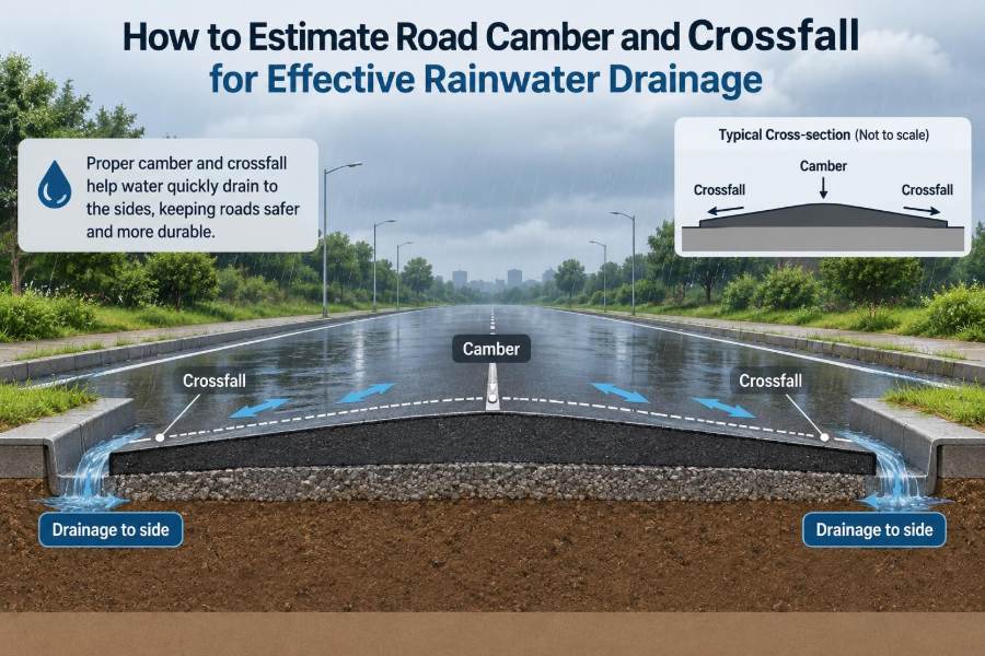

A road can look perfectly smooth on a dry afternoon and still perform badly in the first heavy shower. Water may sit in wheel paths, spread across an intersection, or run toward a property instead of a drain. These are often not paving-material problems; they are geometry problems.
Camber and crossfall give rainwater a controlled path off the carriageway. A small difference in elevation from one side of the pavement to another determines whether runoff reaches a kerb inlet, slows traffic with splash and spray, or remains on the surface long enough to create a skidding risk.
For students, estimating this slope turns a drawing dimension into a practical drainage decision. For site engineers and inspectors, it provides a quick way to check whether constructed levels match the intended drainage behaviour.
The calculation itself is simple. Choosing the right slope, applying it to the correct width, and coordinating it with the wider drainage system require more judgment.
🌧️ What Road Camber Means
Road camber is the transverse shape of a road surface: the slope across the carriageway, generally from a high point toward one or both edges. On a typical two-lane undivided road, the crown at the centreline is highest and each half of the pavement falls toward its kerb or shoulder.
The word is sometimes used loosely to describe either the shape or the numerical slope. In design work, it helps to state both: for example, a crowned pavement with a 2% crossfall on each side.
↔️ Understanding Crossfall
Crossfall, also called cross slope or transverse gradient, is the rate of change in level across a surface, measured perpendicular to the road centreline. It is normally expressed as a percentage, a ratio such as 1 in 50, or occasionally in millimetres per metre.
A 2% crossfall means the surface drops 2 units vertically for every 100 units horizontally. Equally, it drops 20 mm over 1 m, or 1 m over 50 m. These equivalent forms are useful when moving between design drawings, setting-out calculations, and field checks.
🛣️ Camber Shape and Crossfall Value Are Different
Camber describes the overall profile; crossfall describes its slope. A road may have a symmetrical crowned camber, a single-plane slope toward one kerb, or a more complex profile near drainage channels. Each arrangement still has one or more crossfall values.
This distinction matters when estimating levels. A 7 m-wide road with a centre crown has two 3.5 m drainage paths. A 7 m-wide one-way carriageway draining to one edge has one 7 m path. Using the full width in the first case doubles the required level difference.
💧 Why Water Needs a Transverse Escape Route
Rain landing on pavement must first move sideways to the edge before it can enter a gutter, swale, inlet, or side drain. Longitudinal grade then carries it along the road-side drainage line. Crossfall provides the first part of that route.
Even where the road has a good downhill grade, a flat transverse surface can retain shallow water in local depressions. Conversely, a correctly sloped surface cannot solve drainage if the kerb channel is blocked or the outlet is submerged. Pavement drainage is a connected system.
⚠️ Problems Caused by Insufficient Crossfall
Too little slope encourages ponding, especially where construction tolerances, rutting, settlements, or patch repairs have created low spots. The visible result may be a puddle, but the consequences can include splash, reduced tire contact, poor visibility, and moisture entering pavement defects.
Water staying on the surface can also increase the chance of hydroplaning at higher speeds, although tire condition, speed, water depth, and surface texture all influence that risk. In cold climates, retained water may freeze repeatedly and accelerate surface deterioration.
📐 The Core Estimation Formula
The basic relationship is:
vertical fall = crossfall × horizontal widthUse crossfall as a decimal in this equation. For a 2% crossfall, use 0.02. If the width is 3.5 m, the required fall is:
fall = 0.02 × 3.5 = 0.07 m = 70 mmTherefore, the pavement edge should be 70 mm lower than the crown across that 3.5 m half-width. This is an ideal geometric difference before allowing for pavement layers, kerb details, and construction tolerances.
🔢 Converting Percentages, Ratios, and Millimetres
Misreading the form of a gradient is a common source of error. The following reference values show the same slope in several formats.
| Crossfall | Ratio form | Fall per metre | Fall across 3.5 m |
|---|---|---|---|
| 1% | 1 in 100 | 10 mm/m | 35 mm |
| 2% | 1 in 50 | 20 mm/m | 70 mm |
| 2.5% | 1 in 40 | 25 mm/m | 87.5 mm |
| 3% | 1 in 33.3 | 30 mm/m | 105 mm |
A ratio of 1 in 50 does not mean 50%. It means one unit of vertical change for every 50 units of horizontal distance, which is 2%.
🏗️ Start With the Correct Drainage Width
Before calculating, identify the distance over which water actually travels sideways. This is the horizontal distance between the high point and the drainage edge, measured in the cross-road direction.
For a standard crowned road, use the width from crown to kerb line or shoulder break. For a single-slope pavement, use the full width from high edge to low edge. Do not use lane width automatically: the relevant width is controlled by the actual profile and drainage destination.
📍 Finding the Crown or High Point
On a conventional two-way road, the crown often lies near the centreline. It need not be exactly there. A designer may offset it because of widening, lane arrangement, existing levels, drainage constraints, or a transition into a superelevated curve.
Read the typical cross-section and level schedule rather than assuming symmetry. If the crown is offset, calculate each side independently. The two kerb levels may then differ even if the carriageway looks broadly balanced.
🧮 A Simple Crowned-Road Example
Consider a hypothetical 7.2 m carriageway with a centre crown and 2.5% crossfall on both sides. Each drainage width is 3.6 m. The edge fall is:
0.025 × 3.6 m = 0.09 m = 90 mmIf the finished road level at the crown is 102.450 m, each edge level should be 102.360 m, assuming a straight planar fall from the crown. This calculation is separate from the longitudinal levels along the road.
➡️ Estimating a One-Way Crossfall
Single-plane crossfall is common on one-way streets, bridge decks, parking aisles, and situations where drainage must be collected on one side. Suppose a 6.0 m pavement falls at 2% from the high edge to the kerb.
0.02 × 6.0 m = 0.12 m = 120 mmThe low kerb-side edge must be 120 mm below the high edge. This arrangement simplifies runoff direction, but it may increase the flow reaching one gutter, so the kerb and inlet system need adequate capacity.
🧱 Typical Crossfall Ranges, Not Universal Rules
Many paved roads use crossfalls in the low single-digit percentage range. Values around 2% are widely encountered on asphalt and concrete pavements because they usually provide drainage without creating an uncomfortable sideways tilt.
There is no single correct value for every project. Local highway authorities, project specifications, climate, pavement type, speed environment, accessibility requirements, and drainage design govern the adopted crossfall. Always use the applicable standard rather than treating a typical value as a design instruction.
🪨 Pavement Texture Changes the Choice
Smoother, dense surfaces generally need enough slope to prevent thin sheets of water from lingering. Rougher or more open-textured surfaces can store and release some water within their texture, but they still require a defined surface drainage path.
Unsealed roads present a different challenge. Their surface may deform under traffic, and erosion can develop along the fall direction. Their crossfall must drain water while limiting washout and allowing regular maintenance with grading equipment.
🌦️ Rainfall Intensity and Runoff Length
Heavier rainfall makes the drainage path more demanding because more water is moving across the pavement at once. The crossfall is only one control; the distance water travels to the gutter, the longitudinal grade, surface roughness, and inlet spacing all affect water depth at the kerb.
A very wide paved area with a modest crossfall can still create substantial gutter flow. On broad urban roads, designers often consider lanes, parking strips, medians, and local low points together rather than evaluating each strip in isolation.
🧭 Longitudinal Grade Works With Crossfall
Crossfall sends runoff sideways; longitudinal grade sends it along the road. Where a gutter has good longitudinal fall, water can move efficiently toward an inlet. At a sag point or very flat grade, water collects, making inlet location and capacity particularly significant.
Think of a roof valley: its side slopes deliver water to the valley, but the valley itself must still carry water to an outlet. A road kerb channel works in much the same way.
🚰 Kerbs, Gutters, and Drainage Inlets
A calculated edge level is not useful if runoff cannot enter the intended collection feature. Kerb upstands, channel shapes, driveway crossings, and inlet grates all influence the final route.
At the low side, check that the pavement falls continuously into the gutter rather than stopping at a raised lip. Also check that inlets occur before water spreads far enough across the traffic lane to interfere with vehicles, pedestrians, or cyclists during the design storm.
🌀 Superelevation Is Not Ordinary Camber
On a horizontal curve, a road may be superelevated: the entire carriageway is tilted to help vehicles negotiate the curve. This is primarily a vehicle-dynamics feature, although it also determines drainage direction.
During the transition from normal crowned camber to full superelevation, crossfall changes across the road and along its length. These transition zones require careful level design because temporary flat areas or reversed falls can create ponding if the geometry is poorly coordinated.
🔄 Checking Drainage Through Transitions
For each critical station through a transition, identify the high point, low point, and local crossfall. Then trace where water will move. A line that appears to drain on a cross-section may lead into a local hollow when combined with changing longitudinal levels.
Design software and three-dimensional models make this easier, but the engineering question remains simple: can a drop of water follow a continuous descending path to a functioning drain? If not, revise the levels or drainage arrangement.
🚶 Pedestrian Crossfalls Need Extra Care
Footways, crossings, and accessible routes also need drainage, but excessive crossfall can make movement uncomfortable or difficult for wheelchair users, people using mobility aids, and pedestrians with reduced balance. The applicable accessibility criteria may limit crossfall more tightly than the adjacent carriageway requirements.
This creates a design tension near kerbs and building entrances. The solution is often not simply increasing the footway slope; it may involve more frequent drainage points, carefully placed channels, or adjusted finished floor and kerb levels.
🚲 Cycling Facilities Are Sensitive to Surface Shape
Cycle lanes and separated tracks require positive drainage, yet pronounced crossfall can feel unstable, especially to slower riders, children, or riders carrying loads. Grates, channels, joints, and ponding at track edges add further concerns.
Where a cycle facility sits beside a carriageway, do not assume it can share the road’s drainage geometry without review. Its own low points and drainage path should be checked, particularly at driveways, bus stops, and transitions across side roads.
🌉 Bridge Decks Need Deliberate Drainage Detailing
Bridge decks cannot rely on water soaking into shoulders or dispersing across adjacent ground. Their crossfall must direct water toward deck drainage features, and those features must discharge without damaging structural components or areas below.
Expansion joints, waterproofing systems, parapet details, and drainage pipes constrain the geometry. A nominal crossfall calculation remains useful, but bridge drainage should be developed with the structural and hydraulic design, not treated as an ordinary roadside gutter problem.
📏 Survey Methods for Field Verification
On site, crossfall can be checked with a digital level, total station, GNSS equipment where suitable, straightedge and level, or a calibrated cross-slope device. The best method depends on required accuracy, surface condition, and the project’s quality-control process.
Measure at enough points to reveal variation. A single reading may miss a rut, a high asphalt joint, or a local depression. Recording levels at the crown, lane breaks, wheel paths, gutter line, and suspected low spots provides a much more useful picture.
📝 A Practical Calculation Workflow
- Identify the surface type and the applicable project or authority requirement.
- Mark the high point and the intended drainage edge or edges.
- Measure the horizontal drainage width, not merely the nominal road width.
- Convert the specified crossfall percentage to a decimal.
- Calculate fall using crossfall multiplied by width.
- Apply the fall to the known high-point level to obtain the lower level.
- Check longitudinal grade, gutter flow direction, inlets, and local level transitions.
- Verify constructed levels and inspect the surface after rainfall where practical.
This sequence prevents the frequent mistake of treating a transverse calculation as a complete drainage design.
🧰 Setting Out Finished Surface Levels
Once the design levels are known, site teams translate them into string lines, grade stakes, machine-control models, screed references, or survey points. The finished wearing course deserves special attention because small deviations at this final layer directly affect runoff.
Work backward through pavement layer thicknesses when setting formation and base levels. If layer thickness varies unexpectedly, the finished crossfall can change even when lower construction levels appeared correct.
🚧 Construction Tolerances and Real Surfaces
Design drawings represent ideal planes or curves. Constructed surfaces contain tolerances, joints, texture, and local irregularities. A crossfall that is theoretically adequate can still perform poorly if a shallow depression interrupts the drainage path.
Quality checks should therefore assess both average slope and local smoothness. Straightedge testing, level surveys, visual inspection, and controlled water testing can reveal different issues. The governing specification determines acceptance criteria and testing methods.
🕳️ Rutting, Settlement, and Patching Can Reverse the Fall
Traffic loads can form wheel-path ruts, while trench reinstatement or weak support layers can settle. A patch may be placed flush at its edges yet remain slightly low in the middle. Each condition can trap water despite an otherwise compliant original crossfall.
Maintenance decisions should look beyond the defect itself. If standing water repeatedly appears in the same location, investigate profile, drainage blockage, pavement support, and adjacent levels rather than only filling the visible depression.
❌ Common Estimation Mistakes
- Using total width for a crowned road: calculate from crown to each drainage edge.
- Leaving percent as a whole number: 2% is 0.02 in the formula, not 2.
- Measuring sloping distance instead of horizontal width: for ordinary road slopes the difference is small, but design conventions use horizontal plan distance.
- Ignoring the kerb channel: a correctly sloped lane may still discharge poorly at the edge.
- Checking only one cross-section: ponding often occurs where transverse and longitudinal profiles interact.
- Assuming the standard value solves every situation: local geometry and governing requirements still control.
🧪 A Quick Site Ponding Assessment
After rainfall, observe where water remains once normal sheet flow should have drained. Map puddles, note their depth qualitatively or by measurement, and compare their positions with joints, wheel paths, inlets, and surveyed levels.
A controlled water test can be informative during dry weather, but it is not a substitute for a formal hydraulic assessment. Use it to identify flow paths and local barriers, then confirm the cause with levels and drainage inspection.
🏙️ Urban Streets Face Extra Constraints
Urban projects must fit crossfall around frequent driveways, bus stops, raised crossings, utility covers, tree pits, parking bays, and building thresholds. Each feature can interrupt a simple plane and introduce a local drainage problem.
Coordinate levels early between roadway, landscape, utility, and building teams. A late change to a kerb height or footway entrance can force an awkward crossfall adjustment over a short distance, often where accessibility and drainage are already competing.
🌱 Green Drainage Features Change the Outlet, Not the Need for Fall
Bioswales, rain gardens, filter strips, and permeable shoulders can receive runoff instead of sending all of it to a piped network. They can support water-quality and runoff-management objectives when designed for local conditions.
They still need a positive route from pavement to the receiving feature. Ensure the edge detail admits water, soil or aggregate does not block the opening, and overflow is considered for storms beyond the feature’s intended capacity.
🧠 When a Simple Formula Is Not Enough
The basic fall calculation is appropriate for preliminary estimates, routine setting out, and straightforward sections. More detailed analysis may be needed for high-speed roads, wide pavements, low points, major intersections, bridges, complex superelevation, or sites with known flooding concerns.
In those cases, engineers may combine geometric design with runoff calculations, gutter-flow assessment, inlet-capacity checks, and drainage-network modelling. The simple crossfall remains an input, not the entire answer.
✅ A Design and Review Checklist
- Is the selected crossfall permitted by the governing standard and suitable for the surface?
- Does every part of the pavement have a continuous drainage path?
- Are crown positions, lane widths, and edge details accurately represented?
- Do gutter grade and inlet locations manage the resulting flow?
- Are transitions, crossings, access points, and low points checked separately?
- Have pedestrian, cycling, bridge, and maintenance needs been considered?
- Has the final surface, rather than only lower layers, been verified?
🎯 The Core Principle for Effective Road Drainage
Estimating camber and crossfall begins with a direct calculation: multiply the specified slope by the horizontal drainage width. The engineering value comes from choosing the correct high point, measuring the correct width, and connecting the resulting fall to a complete drainage route.
A well-drained road is not necessarily the one with the steepest transverse slope. It is the one whose surface, gutters, inlets, longitudinal profile, and local details work together without creating unsafe, inaccessible, or hard-to-maintain conditions.
Good road drainage is controlled geometry: provide a deliberate fall, preserve it during construction and maintenance, and make sure the water has somewhere reliable to go. 🌧️🛣️📐