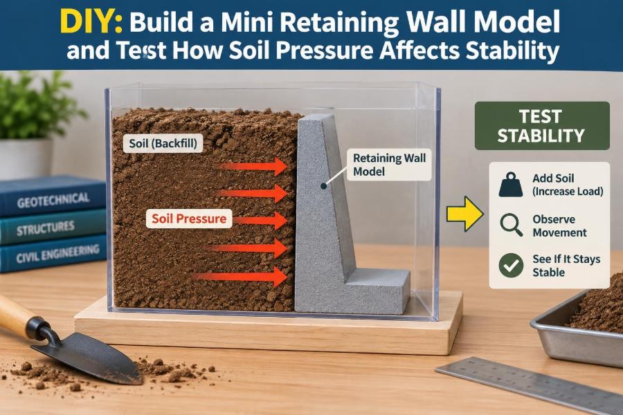

A small retaining wall can make a sloping garden usable, keep a driveway from creeping downhill, or support a road cut through a hillside. It may look like a simple stack of blocks, but the soil behind it is constantly pushing outward and downward.
That pressure changes after rain, with wall height, and with the way the ground is compacted. When the wall cannot resist the resulting forces, it may slide, rotate forward, or allow the ground behind it to settle.
You can observe these ideas without a full-scale construction site. A tabletop model built with a clear container, dry granular material, and a small wall gives you a useful visual experiment in lateral earth pressure.
This DIY activity is not a structural design method for real walls. It is a controlled way to connect classroom mechanics with what engineers inspect in the field: soil movement, drainage, geometry, and stability.
🧱 What a Retaining Wall Actually Does
A retaining wall holds back soil where the ground surface changes elevation. Unlike a freestanding garden border, it must resist a lateral load: a sideways force created by the retained soil.
The wall transfers that load to the foundation soil beneath it. Its stability depends on the wall’s mass and shape, friction at its base, support from the ground in front, and—often most critically—how water is managed behind it.
🎯 The Question Your Model Can Answer
The central question is simple: what happens as soil depth behind a wall increases? Your model should let you add material in measured layers, observe wall movement, and compare conditions rather than merely trying to make the wall fail.
You might test whether a wider base helps, whether a slight backward lean changes behavior, or whether wet material produces a different response. Treat each trial as a comparison: change one main variable and keep the others as consistent as possible.
⚠️ A Scale Model Has Limits
A mini wall does not reproduce every force acting on a real retaining structure. Particle size, wall roughness, water flow, compaction, and the relationship between model dimensions and actual dimensions all affect the result.
For example, sand grains may be large compared with the model wall, while cohesive soil such as clay can behave very differently depending on moisture content. Use the exercise to understand mechanisms and trends, not to calculate safe dimensions for a real project.
🧰 Gather Simple, Reusable Materials
Choose materials that allow you to see movement and make repeatable measurements. A transparent container is especially valuable because it reveals the soil surface and any gaps developing behind the wall.
- Clear plastic storage bin, shallow aquarium, or sturdy transparent box
- Dry, clean sand or fine gravel as the main backfill
- Small wooden blocks, plastic bricks, or a stiff piece of cardboard for the wall
- Ruler, tape measure, marker, and notebook or spreadsheet
- Cardstock or thin plywood for base variations
- Spoon or scoop for placing soil gently
- Optional spray bottle, small weights, protractor, and phone camera
Avoid very fine dusty material, which is unpleasant to handle and can obscure observations. Work over a tray or outdoors if spills are likely.
🛡️ Set Up a Safe, Clean Workspace
Even a small experiment benefits from careful setup. Place the container on a level table and keep water away from power outlets, books, and unprotected electronics.
If using glass, avoid pushing hard on its sides or placing heavy loads on the wall. A plastic container is usually the more forgiving choice. Wash hands after handling soil, especially before eating or touching your face.
📦 Choose a Container That Shows Movement
A useful container is wide enough that the wall is not forced to interact immediately with the far side. If the back wall of the container is too close, it can unintentionally support the soil and distort the experiment.
Place the model retaining wall across the short direction of the container. Leave room behind it for the soil wedge and room in front for the wall to rotate or slide if it becomes unstable.
🏗️ Build a Basic Gravity Wall
Start with a gravity wall, meaning a wall that primarily resists soil pressure through its own weight. Stack blocks tightly, or use a single rigid panel supported by a broad base plate.
For a block wall, make the lower courses wider than the upper courses if possible. That creates a small trapezoidal shape, similar in principle to many masonry gravity walls. Keep the initial wall height modest so you can add soil gradually.
📐 Mark a Baseline Before Adding Soil
Mark the front edge and top position of the wall before every test. You can draw reference lines on the container, tape graph paper behind it, or photograph the setup from the same position.
These references turn vague observations such as “it moved a little” into measurable ones. Record the wall height, base width, backfill depth, and whether the wall began vertical or leaned backward.
🪨 Why Granular Soil Is a Good Starting Material
Dry sand or fine gravel is useful because it flows visibly and produces repeatable slopes when placed in similar ways. Its grains rearrange when the wall moves, making failure patterns easier to see.
Clay-rich soil can also be instructive, but it introduces cohesion: attraction between particles that can allow temporary steep faces or clumps. This may mask the wall-pressure behavior you are trying to isolate in an introductory test.
⏬ Place Backfill in Thin Layers
Add soil behind the wall in shallow, even lifts rather than dumping in a large pile. A sudden pour can strike the wall directly and create an impact load unrelated to normal earth pressure.
After each lift, level the surface gently and note the depth. If you choose to compact the material, use the same number of light taps for every layer. Consistency matters more than achieving a particular density.
📏 Measure Height, Offset, and Rotation
Three simple measurements describe most visible wall movement. Settlement is downward movement, translation is sideways sliding, and rotation is tilting about a point near the base.
Measure horizontal movement at the top and at the toe, the front bottom edge of the wall. If the top moves farther than the bottom, the wall is rotating outward. A small protractor or a photo with a vertical reference line can estimate its change in angle.
🔺 See the Soil Wedge Form
As a wall moves slightly outward, soil immediately behind it tends to settle and shift along a zone that angles upward toward the ground surface. This moving region is often described as an active failure wedge.
In dry sand, look for a faint crack or a differently textured band from the upper back of the wall toward the surface. It may be subtle in a small model, but surface settlement behind the wall is often easier to identify.
➡️ Understand Active Earth Pressure
Soil at rest pushes against a wall even if the wall does not move. If the wall yields slightly away from the soil, lateral stress reduces toward an “active” condition, and the soil mobilizes its shear strength along the moving wedge.
This does not mean the load vanishes. It means the pressure distribution changes as soil particles rearrange. Real design methods account for whether a wall is allowed to move, restrained from movement, or pushed toward the retained soil.
⬅️ Know Why Restrained Walls Face Higher Loads
A basement wall connected to a stiff floor system cannot easily move outward. Soil pressure in that condition is commonly closer to at-rest earth pressure, which can be greater than active pressure for the same soil and geometry.
You can approximate restraint in your model by bracing the top of the wall against the container. The comparison helps explain why a flexible garden wall and a rigid below-grade wall should not automatically be treated as the same engineering problem.
💧 Add Water Only as a Separate Test
Water makes the experiment more realistic but less controlled. First complete dry trials. Then, in a fresh setup, mist the backfill lightly or add water slowly near the rear of the container while watching for seepage and surface changes.
Do not assume wet soil is always stronger or always weaker. Small amounts of water can create apparent cohesion in sand, while saturation can increase loads and reduce effective interparticle contact. The outcome depends on drainage and soil type.
🌊 Pore Water Pressure Changes the Problem
Water in soil pores can exert pressure independently of the soil grains. This pore water pressure adds to the lateral demand on a wall and can reduce the frictional resistance between grains.
In the model, trapped water may make the material appear to push more fluidly against the wall. On a real site, drainage layers, perforated pipes, filter fabric, and weep holes are often used to prevent water pressure from building up behind suitable wall systems.
🚰 Drainage Is Not an Optional Detail
A wall designed only for dry soil can perform poorly when rainwater is unable to escape. Drainage does not eliminate soil pressure, but it helps avoid adding a large water-related component to the load.
For a demonstration, create two identical dry-sand setups. In one, place a narrow gravel zone behind the wall leading to a small outlet path. In the other, use finer material with no outlet. Add water slowly and compare where it collects and how the wall responds.
⚖️ Test the Effect of Wall Weight
Add small, evenly placed weights to the top or build the wall from denser blocks. A heavier gravity wall generally has more resistance to sliding and overturning, provided the foundation soil can support it.
More weight is not a universal fix. It can increase bearing pressure beneath the base and may not solve a drainage problem. In your model, compare the amount of backfill needed to cause first visible movement with and without added weight.
📐 Test a Wider Base
A wider base can improve stability in several ways. It increases the contact area with the foundation, can provide a longer lever arm against overturning, and may increase resistance to sliding through base friction.
Make two walls of the same height and mass where practical, but attach a wider base plate to one. Keep the base surface material the same. Observe whether rotation begins later and whether sliding becomes less noticeable.
↩️ Try a Small Backward Batter
Batter is a deliberate slope in the wall face. A wall that leans slightly back toward the retained soil may position its weight more favorably relative to the overturning force.
Use a spacer under the front or back of the base to create a modest, repeatable angle. Too much tilt makes comparison difficult and can alter how the soil is placed. The point is to observe a geometric effect, not to find a magic angle.
🧲 Explore Base Friction and Sliding
Set the same model wall on different base surfaces, such as smooth plastic, sandpaper, or a thin layer of compacted sand. Then use identical backfill placement. The wall on the smoother surface may slide more readily.
In full-scale work, engineers evaluate sliding resistance using the wall base, foundation soil properties, and sometimes a shear key—a projection below the base that engages soil. A toy model can illustrate the principle but cannot supply dependable design values.
🦶 Watch the Toe and Heel
The toe is the portion of a wall base extending in front of the wall stem; the heel extends beneath the retained soil. These terms are particularly useful for reinforced concrete cantilever walls.
When soil pressure pushes a wall forward, the toe-side foundation contact can increase while contact near the heel may reduce. In a transparent model, watch for soil disturbance at the front edge and for any visible lifting or separation behind the base.
🧱 Compare Gravity and Cantilever Concepts
A gravity wall relies mainly on mass. A reinforced concrete cantilever wall uses a vertical stem and a base slab shaped to act as a structural lever, with steel reinforcement carrying tensile forces inside the concrete.
Your blocks most closely represent a gravity wall. A flat base plate extending behind a thin upright panel can loosely demonstrate a cantilever-like geometry, but it will not model reinforcement behavior. Keep the distinction clear when interpreting results.
| Wall concept | Main resistance mechanism | Useful model observation |
|---|---|---|
| Gravity wall | Self-weight and broad base | Effect of added mass and base width |
| Cantilever wall | Reinforced stem and base action | Role of toe and heel geometry |
| Mechanically stabilized earth wall | Reinforcement layers within fill | How soil and reinforcement act together |
🕸️ Demonstrate Reinforced Soil Carefully
To model reinforced soil, place horizontal strips of coarse mesh, open-weave fabric, or paper strips between thin layers of sand behind the wall. Extend the strips back into the fill, keeping their spacing consistent.
The strips can limit movement by transferring load into a larger mass of soil. In real mechanically stabilized earth systems, reinforcement type, length, connection details, backfill quality, and facing design are engineered together. Household materials only show the basic interaction.
🚗 Add a Surcharge Load
A surcharge is an extra load applied at the ground surface behind a wall. It may come from a vehicle, stored material, a nearby foundation, or sloping ground. This load can increase lateral pressure.
In the model, place a small, flat weight on the soil surface some distance behind the wall, then move it progressively closer in separate trials. A weight placed near the wall is more likely to influence its behavior than one well outside the active soil zone.
⛰️ Change the Slope Behind the Wall
Level backfill is a useful baseline, but retained ground is often sloped. Build a gently rising surface behind your wall and compare it with a level surface using the same wall and soil depth.
A slope adds soil within the region that can contribute to lateral loading. Keep the slope stable while building it; if it avalanches before the wall moves, you are observing slope instability rather than a clean retaining-wall comparison.
📝 Use a Repeatable Test Procedure
A structured method makes your findings more useful. Reset the container between trials, because disturbed soil retains a history of movement and density changes.
- Record the wall geometry, base condition, and soil type.
- Set the wall vertical or at the selected batter and mark reference positions.
- Add backfill in equal layers, recording each depth.
- Measure top and base movement after each layer.
- Note cracks, settlement, sliding, tilting, and water behavior if relevant.
- Stop when movement becomes rapid or the wall loses its intended shape.
- Repeat with one planned variable changed.
📊 Create a Clear Observation Table
A simple log helps you separate what you saw from what you think caused it. Photographs taken from the same angle after each layer can support measurements and reveal gradual rotation that is hard to notice in real time.
| Trial | Changed variable | Backfill depth at first movement | Movement pattern | Notes |
|---|---|---|---|---|
| 1 | Baseline wall | Record your value | Sliding, rotation, or both | Surface cracking, settlement, and soil condition |
| 2 | Wider base | Record your value | Compare with Trial 1 | Keep soil placement consistent |
| 3 | Water or surcharge | Record your value | Compare with dry baseline | Describe drainage and moisture |
🔍 Distinguish Failure Modes
Not every unstable wall fails in the same way. Identifying the mode matters because different remedies address different causes.
- Sliding: the whole wall shifts forward with limited rotation.
- Overturning: the top moves outward and the wall rotates around the toe region.
- Bearing failure: foundation soil deforms excessively beneath the base.
- Global instability: a larger mass of wall and soil moves along a deep slip surface.
- Internal failure: components within a reinforced wall system pull out, tear, or yield.
Your tabletop setup will most often show sliding or overturning. A lack of dramatic collapse does not mean the model was fully stable; small movements can be the first warning.
❌ Common Experimental Mistakes
The most common error is changing several conditions at once—using wetter soil, a wider base, and a different wall height in the same comparison. That makes the result difficult to explain.
Other frequent problems include pouring soil directly against the wall, measuring only at the end, and failing to rebuild the soil bed between tests. Also avoid treating a temporary arch or clump in damp sand as evidence that water has made the system safe.
🧠 Interpret Results as Cause and Effect
Suppose a wider-base wall tilts less at the same soil depth. A reasonable interpretation is that its geometry improved resistance to rotation and perhaps sliding. It does not prove that every wider wall is safe on every soil.
Likewise, if water causes earlier movement, the likely contributors may include added water pressure, altered particle friction, or erosion of the base material. State what you observed, then identify plausible mechanisms without claiming more precision than the model provides.
🏡 Connect the Model to Real Projects
On real sites, retaining-wall design starts with information the tabletop model cannot supply: soil layering, groundwater conditions, slope geometry, seismic considerations where applicable, nearby loads, and foundation capacity.
Engineers also consider construction sequence. Excavating at the toe, placing fill poorly, or blocking drainage can change conditions after a wall is built. For walls supporting buildings, roads, steep slopes, or public areas, professional assessment is essential.
📐 Why Calculations Still Matter
Physical models build intuition, but engineering design requires quantitative checks. Depending on the wall type and site, these commonly include sliding, overturning, bearing pressure, structural strength, overall slope stability, drainage, and settlement.
Designers use measured or conservatively selected soil parameters and apply the governing building requirements for the location. A model cannot replace site investigation because two soils that look similar in a bin may have very different strength and drainage behavior in the ground.
🌱 Extend the Activity for Deeper Learning
Once your baseline method works, try a focused research question. For example: does equal wall mass perform differently when concentrated low in the wall rather than high in the wall? Or, how does the location of a surcharge alter observed rotation?
Another useful extension is to draw soil-surface profiles before and after each test. Comparing those profiles with wall displacement helps connect a visible settlement zone to the idea of a mobilized soil wedge.
✅ The Core Principle: Wall, Soil, Water, and Ground Act Together
A retaining wall is never just a wall. Its behavior emerges from the interaction of wall geometry, retained soil, water conditions, foundation support, surface loads, and construction quality.
Your miniature experiment makes that interaction visible: more retained height tends to increase lateral demand; a wall that can move may rotate or slide; drainage can change the loading condition; and geometry can change the available resistance. The lesson is not to copy model dimensions outdoors, but to recognize why each part of a real retaining system deserves deliberate design.
A stable retaining wall comes from managing the entire soil–water–structure system, not from relying on blocks alone. Build carefully, observe patiently, and let each trial sharpen your engineering judgment. 🌉🧱💧