
A bridge can look simple from a passing car: a deck, guardrails, piers, and a view of the river or roadway below. Yet that apparently simple crossing is the visible result of years of investigation, design decisions, temporary works, inspections, and carefully sequenced construction.
For civil engineers, a bridge project is never just a question of spanning a distance. It must carry specified loads, fit its site, tolerate weather and ground movement, remain inspectable, and be built safely with the equipment and materials available.
The sequence matters. A small error in survey control can shift a pier. An incomplete ground investigation can change the foundation solution. A poorly planned traffic diversion can make an otherwise sound design difficult to build.
Following the project from its earliest survey to handover reveals why modern bridge construction is a coordinated engineering process rather than a single spectacular concrete pour or steel lift.
🧭 The bridge begins with a problem to solve
A project usually starts with a transport need: connecting communities separated by a river, removing a dangerous level crossing, replacing a deteriorated structure, or carrying a new road over rail lines. The desired outcome defines the early constraints.
Engineers identify who and what must cross: pedestrians, cyclists, emergency vehicles, freight traffic, rail vehicles, utilities, or wildlife. They also establish the obstacle below and the required clearance above it.
🗺️ Choosing the corridor and crossing location
The shortest crossing is not always the best crossing. A narrow river reach may have poor ground conditions, lie in a floodplain, conflict with protected habitat, or require sharp and unsafe approach curves.
Early route studies compare alternatives using constructability, land access, environmental effects, utility conflicts, future maintenance, and connections to the existing network. The preferred alignment balances these competing demands rather than optimizing only one.
📐 Establishing survey control
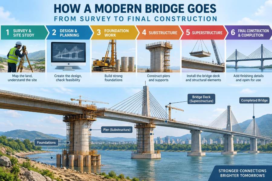
Surveyors create a reliable spatial reference for the whole project. They establish control points tied to an approved coordinate system and use them to map terrain, buildings, roads, watercourses, and existing structures.
Control is protected and checked throughout construction. Setting out a pier from an unverified point can produce an alignment error that affects bearing locations, girder fit-up, and deck geometry.
🔎 Recording the existing site
Topographic survey records levels and visible features, while utility surveys seek buried pipes, cables, ducts, and chambers. Existing records help, but their accuracy and completeness must be treated cautiously until verified.
For a bridge over a railway or highway, the survey also captures clearance envelopes, access routes, drainage paths, and locations suitable for cranes or temporary supports.
🌊 Understanding water, wind, and climate
At a water crossing, hydrologic and hydraulic assessment estimates how water moves through the site during ordinary flows and flood events. Engineers consider water level, velocity, debris, channel movement, scour, and effects of the proposed piers or abutments.
Wind, temperature range, ice where relevant, seismic conditions, and corrosion exposure also influence design. A coastal bridge and an inland overpass may use similar forms, but their durability details can be very different.
🪨 Investigating the ground below
Ground investigation is one of the most consequential early activities. Boreholes, trial pits, in-situ tests, laboratory testing, and groundwater observations help engineers develop a ground model.
That model is an interpretation, not a guarantee. Soil and rock vary naturally, so foundation designs include appropriate allowances and construction teams remain alert for conditions that differ from the investigation.
🏗️ Selecting the structural form
The span length, clearance, foundation conditions, visual setting, construction access, and budget guide the structural concept. Common options include reinforced or prestressed concrete girders, steel plate girders, box girders, trusses, arches, cable-stayed bridges, and suspension bridges.
A modest road overbridge may suit precast concrete beams. A long crossing with few permissible supports may require a more complex solution. The “best” bridge is the one that performs safely over its life and can realistically be built at that site.
⚖️ Defining the design loads
Bridge components are designed for more than the self-weight of concrete and steel. Engineers consider traffic or rail loading, pedestrians, wind, temperature effects, braking and acceleration, construction loads, settlement, water forces, collision risks, and sometimes seismic effects.
Load combinations matter because actions can occur together. Design standards specify how these are considered, but the project team must still understand the physical behavior behind the calculations.
📊 Comparing common bridge systems
| System | Typical strength | Key construction consideration |
|---|---|---|
| Precast concrete girder | Efficient for many short to medium spans | Transport routes and crane capacity limit beam size |
| Steel plate girder | Relatively light for its span capability | Fabrication quality and corrosion protection are critical |
| Cast-in-place box girder | Can suit curved or continuous alignments | Falsework, form travelers, or staged pours need careful planning |
| Cable-stayed bridge | Allows long spans with few supports | Geometry control and balanced erection are essential |
These are broad comparisons, not selection rules. Local material supply, labor capability, access, and whole-life maintenance can change the preferred option.
🧮 Turning a concept into a design model
Structural analysis models estimate reactions, forces, deflections, and movements under the required load cases. Engineers then design decks, girders, diaphragms, piers, bearings, foundations, and connections to transfer loads safely to the ground.
Models simplify reality. Good design therefore includes independent checking, sensible assumptions, detailing review, and engineering judgment rather than unquestioning reliance on software output.
🔩 Detailing the connections and interfaces
Many construction problems arise at interfaces: where a bearing meets a pier cap, where a drainage outlet passes through a diaphragm, or where reinforcement conflicts with an embedded item.
Detailed drawings and coordinated three-dimensional models help resolve these issues before site work begins. Clear tolerances are particularly important because fabricated steel, precast units, and cast concrete all have permitted dimensional variation.
🛤️ Designing approaches and transitions
A bridge is part of a route, not an isolated object. Approach embankments, retaining walls, pavement, drainage, barriers, lighting, and tie-ins must work with the structure.
Settlement near abutments is a familiar challenge. If soft ground compresses under an approach embankment, a bump can develop at the bridge end. Ground improvement, staged filling, transition slabs, or other measures may be needed.
🌱 Environmental planning and permissions
Bridge work can affect water quality, fish passage, vegetation, noise, air quality, heritage features, and nearby residents. Project requirements may limit working seasons, prohibit in-channel work during sensitive periods, or require specific erosion and sediment controls.
Environmental commitments must appear in the construction plan, not merely in approval documents. A practical measure is only effective when crews understand when and how to apply it.
🚧 Planning traffic, rail, and public safety
Building over an active road or railway introduces a second operating system beneath the work. Lane closures, possessions, protective screens, lifting restrictions, and emergency access arrangements are planned with the relevant authority.
Temporary traffic management should be treated as engineering work. Poorly arranged diversions can create congestion, unsafe merging, reduced access for emergency services, and pressure on nearby local streets.
📦 Procuring materials and specialist work
Long-lead items can shape the schedule. Structural steel, bearings, expansion joints, precast girders, stay cables, specialized formwork, and large mechanical components may need substantial time for design approval, fabrication, testing, and delivery.
Specifications define required properties, but inspection and documentation verify that supplied products match the approved design. Material traceability is especially valuable for structural components and reinforcement.
🏕️ Setting up the construction site
Before permanent bridge work begins, contractors establish access, fencing, welfare facilities, storage areas, lifting zones, power, drainage controls, and emergency arrangements. The site layout changes as work progresses, so it must be managed rather than assumed fixed.
Temporary works often occupy more space than the finished bridge. Crane pads, falsework, cofferdams, working platforms, and material storage all need stable ground and safe access.
🧱 Building foundations
Foundation choice depends on the ground model and loads. Shallow foundations spread load near the surface where competent material exists. Deep foundations, such as driven piles or bored piles, transfer load to deeper strata or mobilize resistance along their length.
For piers in water, a cofferdam or other temporary enclosure may create a workable dry area. Dewatering must be controlled because uncontrolled groundwater movement can destabilize excavation sides or affect nearby ground.
🧪 Checking concrete, piles, and reinforcement
Quality control starts before concrete arrives. Teams check excavation level, pile records, reinforcement size and spacing, cover to reinforcement, formwork condition, embedded items, and cleanliness.
Fresh concrete is checked according to the project requirements, then placed, compacted, finished, and cured correctly. Test specimens and records support verification, but they do not replace good placement practice on the day.
🏛️ Constructing abutments and piers
Abutments retain approach fill and support the bridge ends; piers support the structure between them. Their construction usually involves reinforcement cages, formwork, concrete pours, curing, and survey checks.
Tall piers may be cast in lifts. Construction joints require preparation so successive pours act together as intended, while pour rates must be compatible with formwork pressure and the concrete mix behavior.
🪜 Temporary works carry real risk
Temporary works include falsework, formwork, scaffolds, shoring, access platforms, lifting frames, and excavation support. They may exist for weeks, but their failure can be as serious as failure of a permanent component.
A competent temporary works process defines the design, checks, inspection responsibilities, loading limits, and authorization for use. Changes in the field should not be improvised simply because a temporary arrangement appears convenient.
🏗️ Erecting girders or building the superstructure
The superstructure is the part spanning between supports. Precast beams may be lifted into place by cranes; steel girders may arrive in segments and be bolted or welded; a concrete box may be built on falsework or advanced in stages.
Erection is governed by more than the final design. Engineers check lifting points, temporary bracing, crane reach, wind limits, sequence, stability before diaphragms are complete, and the capacity of access roads and crane pads.
🎯 Controlling geometry during erection
Bridges move under their own weight, temperature changes, and later construction stages. Survey teams monitor line, level, camber, pier position, and bearing elevations so the completed bridge reaches its intended profile.
On a long or staged structure, small deviations can accumulate. Geometry control is therefore a continuing feedback process: measure, compare with predicted behavior, investigate differences, and adjust only through approved methods.
🧷 Bearings and expansion joints allow movement
Concrete shrinks and creeps, steel and concrete expand with heat, and supports may rotate slightly under load. Bearings transfer loads while allowing specified movement or rotation; expansion joints accommodate deck movement at selected locations.
These components are often small compared with girders, but they demand careful installation. Incorrect levels, debris, poor drainage, or inaccessible details can create difficult maintenance problems later.
🛣️ Placing the deck, waterproofing, and surfacing
For many bridges, a reinforced concrete deck slab forms the riding surface support and distributes wheel loads to the main girders. Its reinforcement, screed rails, pour sequence, finishing, and curing affect both strength and long-term durability.
Once the deck is ready, waterproofing and surfacing protect it from water and traffic wear. Drainage outlets must be clear and directed appropriately; standing water is an early route to deterioration.
🧰 Adding the operational components
Parapets, barriers, railings, lighting, signs, inspection access, drainage, utilities, and protective coatings turn a structural frame into an operating asset. Each item affects safety, maintenance, and user experience.
For example, a drainage pipe should not discharge onto a bearing or pier surface where it can concentrate water and contaminants. Durable bridges manage water deliberately.
🔍 Inspection, testing, and handover
Inspection occurs throughout construction, but final handover brings records together: as-built surveys, material certificates, concrete and weld documentation, test results, inspection reports, operating information, and maintenance requirements.
Some projects include proof loading or other commissioning checks where appropriate. A successful handover means the owner understands what was built, where critical components are located, and how they should be inspected.
🛡️ Designing for inspection and maintenance
A bridge should be maintainable without extraordinary effort. Designers consider access to bearings, drainage, joints, lighting, enclosed spaces, and critical steelwork, as well as safe routes for inspectors.
Durability is not only a material choice. Adequate cover, sensible drainage, corrosion protection, joint detailing, and avoidance of water traps often determine whether routine maintenance remains manageable.
⚠️ Common coordination failures to avoid
- Treating survey data as permanent truth: control and site conditions must be verified as work advances.
- Leaving temporary works until late: erection stability and access influence the permanent design.
- Ignoring drainage details: water can damage decks, bearings, approaches, and substructures.
- Designing inaccessible components: difficult inspection usually means deferred maintenance.
- Separating design from construction sequence: a structure safe in its final state may be vulnerable during erection.
🤝 Why bridge delivery is a team process
Surveyors, geotechnical engineers, structural designers, highway engineers, environmental specialists, fabricators, contractors, inspectors, and asset managers all see different parts of the same problem. Good communication connects their decisions.
Constructability reviews are especially useful because they ask practical questions early: Can this reinforcement be fixed? Can the crane reach? Where will water go during a storm? Can an inspector reach this bearing in twenty years?
🌉 The core principle: build the whole system, not just the span
A modern bridge succeeds when its investigations, foundations, structural form, construction sequence, drainage, approaches, safety systems, and maintenance access support one another. The visible deck is only one part of that system.
From the first control point to the final inspection file, decisions should preserve a clear load path, reliable geometry, safe construction stages, and durable details. That is how a crossing becomes dependable infrastructure rather than simply a structure that looks complete.
The essential lesson is that a bridge is built twice: first through coordinated investigation and design, then through controlled construction that respects the realities of the site. 🌉🦺📐